
Diagnostic Command is it Bugged?
Seems I have a bit of a theme going on at the moment with my obsession with Amstrad CPC related tech, and today’s article is no exception.
Back in the later 80’s, using my knowledge of the FDC Controller in my previous blog entry
I created a disk protection system, called “JaceLock”, I will go into the details of this in a future entry.
The reason the disk couldn’t be copied by commercial copiers was related to a potential Bug in the disk controller implementation. At least that’s what I thought back in ’89… This is why I need your help. If you have an Amstrad CPC with 3″ Disk Drive Attached and… a Gotek device or other method of getting external files to your machine like The Duke’s M4. I would love for you to test this out and send me the results.
I have created a DSK and HFE Image that can be loaded into either an Emulator, M4 or GOTEK Connected Device available for download here.
The disk image contains the following files. The one you’re interested in is TYPEIN.BAS

Alternatively if you want to go old school, I’ve provided a BASIC type-in and Assembly Language Listing below.
Instructions :-
Add the .DSK or .HFE file to your GOTEK or M4 Device and mount it.
LOAD"TYPEIN.BAS"
RUN
The program will Poke memory for the specific FDC Routine, and will save a file to disk called “DiskData.bin”. It doesn’t matter what disk is in the drive as long as it can be read (i.e it’s formatted).
The program simply runs the Diagnostic Command on TRACK 0 of DRIVE A: and then saves the data to file for post analysis. The email address to send the final file back to me is included in the program on the disk. Had to do this to try and reduce spam…
If your GOTEK is Drive A: and your Physical Disk is in Drive B, enter the following
80 POKE &9D20,1:CALL &9D00:SAVE"diskdata",b,&7A00,8192
Amstrad CPC Type-In Listing
5 ' Read Track Test, Please send DSK File to ***redacted***
10 LN=80:D=0:MEMORY &9CFF:AD=&9D00:L=&156
20 IF D=0 THEN GOSUB 70
30 READ a$:POKE AD+P,VAL("&"+a$)
40 D=D+1:ch2=ch2+VAL("&"+a$):IF D=16 THEN D=0:IF ch1<>ch2 THEN PRINT"CHECKSUM ERROR in line ";LN:STOP ELSE LN=LN+10:ch2=0:ch1=0
50 P=P+1:IF P=L THEN GOTO 80
60 GOTO 20
70 READ a$:ch1=VAL("&"+a$):RETURN
80 CALL &9D00:SAVE"diskdata",b,&7A00,8192
90 PRINT "Thank you for your help, ***Redacted****"
100 DATA 0596,F3,01,7E,FA,3E,01,ED,79,21,00,00,06,02,2B,7C,B5
110 DATA 04B3,20,FB,10,F9,11,00,00,CD,45,9D,21,00,7A,16,00,1E
120 DATA 06BC,00,F3,7B,32,55,9E,CD,45,9D,7B,32,41,9E,7A,32,42
130 DATA 08FD,9E,11,3F,9E,CD,BF,9D,CD,DE,9D,CD,1C,9E,01,7E,FA
140 DATA 09C3,AF,ED,79,C9,00,F5,C5,D5,E5,7B,F6,20,32,44,9D,CD
150 DATA 076E,9E,9D,3A,3D,9E,92,28,13,7A,B7,28,14,CD,AD,9D,CD
160 DATA 0950,9E,9D,21,44,9D,3A,3C,9E,BE,20,F4,E1,D1,C1,F1,C9
170 DATA 08BB,CD,92,9D,AF,CD,7E,9D,7E,E6,10,28,F8,18,ED,3A,55
180 DATA 075E,9E,32,4B,9E,11,49,9E,CD,BF,9D,21,3E,9E,CD,1C,9E
190 DATA 074B,2B,C9,11,52,9E,3A,55,9E,32,54,9E,C3,BF,9D,D5,11
200 DATA 0889,50,9E,CD,BF,9D,21,3C,9E,CD,1C,9E,D1,C9,D5,32,4F
210 DATA 07A8,9E,3A,55,9E,32,4E,9E,11,4C,9E,CD,BF,9D,D1,C9,01
220 DATA 08FA,7E,FB,C5,1A,F5,13,ED,78,87,30,FB,FA,C6,9D,1A,0C
230 DATA 075F,ED,79,0D,3E,05,3D,20,FD,F1,3D,20,E8,C1,C9,3A,55
240 DATA 0865,9E,F6,20,32,FB,9D,01,7E,FB,ED,78,FE,C0,38,06,0C
250 DATA 08D6,ED,78,77,0D,23,ED,78,F2,F5,9D,E6,20,20,F1,C9,01
260 DATA 065C,7E,FB,3A,55,9E,F6,20,32,18,9E,18,06,0C,7E,23,ED
270 DATA 0890,79,0D,ED,78,F2,12,9E,E6,20,20,F1,C9,3A,55,9E,F6
280 DATA 0785,10,32,38,9E,ED,78,FE,C0,38,FA,0C,ED,78,77,0D,23
290 DATA 05D3,3E,05,3D,20,FD,ED,78,E6,10,20,E9,C9,00,00,00,09
300 DATA 01D3,62,00,00,00,01,06,01,52,FF,02,04,00,03,0F,00,00
310 DATA 0012,01,08,02,07,00,00
Assembly Listing for the Test.
You’re curious, and that’s a good thing, so here’s the assembly listing for above for your reference. It’s a quickly cut down version of the main FDC Code.
;
         ORG  #9d00                     ; Alternative DDFDC Commands
         ;ENT  $                         ; Version 9.89 - Jason Brooks
motoron
         DI
         LD   bc,#fa7e
         LD   a,1
         OUT  (c),a
         LD   hl,0
         LD   b,2
motoron1                                ; Pause Loop To Allow Motor To Pick Up
         DEC  hl
         LD   a,h
         OR   l
         JR   nz,motoron1
         DJNZ motoron1
         ld de,0
         call movtrak
         LD   hl,#7a00
         LD   d,0
         LD   e,0
readtrak
         DI
         LD   a,e
         LD   (drive),a
         CALL movtrak
         LD   a,e
         LD   (READ_TRACK+2),a
         LD   a,d
         LD   (READ_TRACK+3),a
         LD   de,READ_TRACK
         CALL ddfdccom
         CALL ddfdcexc
         CALL ddfdcres
motoroff
         LD   bc,#fa7e
         XOR  a
         OUT  (c),a
         RET                            ; Quit All Reg. Intact
;
;                        **** Move Drive Head To Track T ****
;
drivicl  DEFB 0
movtrak                                 ; On Entry D = Destination Track
         PUSH af
         PUSH bc
         PUSH de
         PUSH hl                        ; Preserve Registers
         LD   a,e
         OR   #20
         LD   (drivicl),a
         CALL senseint                  ; Get Current Track Position
         LD   a,(sense+1)
         SUB  d                         ; Is Destination Track Current Track ?
         JR   z,movtrake                ; If So Quit
         LD   a,d                       ; A = Track
         OR   a                         ; Is Destination Track 0
         JR   z,trak0                   ; If So Then Trak0
         CALL seek                      ; Give DDFDC SEEK Command
movtrak1                                ; Use This Since No DMA
         CALL senseint                  ; Has Drive Reached Destination ?
         LD   hl,drivicl
         LD   a,(sense)
         CP   (hl)
         JR   nz,movtrak1               ; If Not Loop movtrak1
movtrake                                ; Quit Routine
         POP  hl
         POP  de
         POP  bc
         POP  af
         RET                            ; Preserved Registers
trak0
         CALL recalib                   ; Recalibrate (Move To Track 0)
         xor a
trak01
         CALL senseds                   ; Call SENSE DRIVE STATUS
         LD   a,(hl)
         AND  %10000                    ; Has Drive Head Reached TRK 0
         JR   z,trak01                  ; If Not Loop
         JR   movtrake                  ; Restore Regs & Quit
;
;                       **** SENSE DRIVE STATUS ****
;
senseds
         LD   a,(drive)
         LD   (SenseCde+2),a
         LD   de,SenseCde
         CALL ddfdccom
         LD   hl,sendst                 ; Pointer To Put Resultant Data
         CALL ddfdcres
         DEC  hl                        ; On Exit HL=Address Of Status Reg. 3
         RET                            ; Quit
;
;                  **** RECALIBRATE DRIVE HEAD (TRACK 0) ****
;
recalib                                 ; Recalibrate
         LD   de,RECALCOM
         LD   a,(drive)
         LD   (RECALCOM+2),a
         JP   ddfdccom
;
;                       **** SENSE INTERUPT STATUS ****
;
senseint                                ; Sense Interupt Status
         PUSH de                        ; Preserve DE
         LD   de,SENSE_INT
         CALL ddfdccom
         LD   hl,sense
         CALL ddfdcres                  ; Call & Quit
         POP  de
         RET
;
;                   **** SEEK COMMAND MOVE TRACK HEAD ****
;
seek                                    ; SEEK Entry D=Track
         PUSH de
         LD   (Seek_DT+3),a
         LD   a,(drive)
         LD   (Seek_DT+2),a
         LD   de,Seek_DT
         CALL ddfdccom
         POP  de
         RET
;
;                        **** DDFDC COMMAND PHASE ****
;
ddfdccom                                ; DDFDC Command Phase
         LD   bc,#fb7e
         PUSH bc
         LD   a,(de)                    ; Get Number Of Parameters
ddfdc
         PUSH af                        ; Preserve Counter
         INC  de
ddfdc1                                  ; Is Drive Ready To Accept Command ?
         IN   a,(c)
         ADD  a,a
         JR   nc,ddfdc1
         JP   m,ddfdc1                  ; If Not Then Wait
         LD   a,(de)
         INC  c
         OUT  (c),a                     ; Give DDFDC Command @ Port #FB7F
         DEC  c
         LD   a,5
ddfdcp                                  ; Wait 13 uS
         DEC  a
         JR   nz,ddfdcp
         POP  af
         DEC  a
         JR   nz,ddfdc
         POP  bc                        ; On Return BC=#FB7E
         RET                            ; Quit
;
ddfdcexc                                ; DDFDC Execution Phase - DATA IN
         LD   a,(drive)
         OR   #20
         LD   (ddfdexc2-1),a
ddfdcexd
         LD   bc,#fb7e
         IN   a,(c)
         CP   #c0
         JR   c,ddfdexc1
ddfdexc0
         INC  c                         ; Point To #FB7F - DATA REGISTER
         IN   a,(c)                     ; Get byte from port
         LD   (hl),a                    ; Store it
         DEC  c                         ; Restore Port To Main Status Reg.
         INC  hl                        ; HL+1
ddfdexc1
         IN   a,(c)
         JP   p,ddfdexc1                ; Drive Not Finished Output So Wait
         AND  #20                       ; Main Status Reg=Execution Phase Start
ddfdexc2
         JR   nz,ddfdexc0               ; If Not Finished Loop ddfdexc
         RET                            ; Else Quit
;
;              **** DDFDC EXECUTION PHASE DATA TO SYSTEM ****
;
ddfdcwri                                ; DDFDC Write Into Data Register
         LD   bc,#fb7e                  ; Point To MAIN STATUS REG
         LD   a,(drive)
         OR   #20
         LD   (ddfdcw3-1),a
         JR   ddfdcw2                   ; Wait Till DDFDC Ready.
ddfdcw1
         INC  c                         ; Point To Data Port
         LD   a,(hl)                    ; Get Byte To Place
         INC  hl                        ; HL+1
         OUT  (c),a                     ; Output To Port #FB7F
         DEC  c                         ; Restore Port
ddfdcw2
         IN   a,(c)
         JP   p,ddfdcw2                 ; If Drive Not Ready Loop ddfdcw2
         AND  #20
ddfdcw3
         JR   nz,ddfdcw1                ; Is All Output Finished ?
         RET                            ; Quit
;
;                       **** DDFDC RESULTS PHASE ****
;
ddfdcres                                ; DDFDC Result Phase
         LD   a,(drive)
         OR   #10
         LD   (ddfdresq-1),a
ddfdcret
         IN   a,(c)
         CP   #c0                       ; Is DDFDC Ready ?
         JR   c,ddfdcret                ; If Not Wait
         INC  c
         IN   a,(c)                     ; Get Byte From DATA REG
         LD   (hl),a                    ; Store it
         DEC  c                         ; Restore Data Reg.
         INC  hl                        ; HL+1
         LD   a,5
ddfdresp                                ; Wait 13 uS
         DEC  a
         JR   nz,ddfdresp
         IN   a,(c)
         AND  #10                       ; Has Results Finished ?
ddfdresq
         JR   nz,ddfdcret               ; If Not Loop ddfdcres
         RET                            ; Quit
;
;                  **** DATA AREA BUFFERS, POINTERS Etc. ****
;
sense                                   ; Data from RESULT PHASE OF SNSE INT ST
         DEFB 0                         ; ST0
         DEFB 0                         ; Present Track Number
;
;             **** BYTE FOR SENSE DRIVE STATUS RESULT PHASE ****
;
sendst   DEFB 0                         ; Status Register 3
;
;             **** DATA FOR COMMAND PHASE OF FORMAT A TRACK ****
;
READ_TRACK
         DEFB 9
         DEFB %1100010
         DEFB 0
         DEFB 0
         DEFB 0
         DEFB 1
         DEFB 6
         DEFB 1
         DEFB #52
         DEFB #ff

;
;            **** COMMAND DATA FOR SENSE DRIVE STATUS ****
;
SenseCde
         DEFB 2                         ; 2 Parameters
         DEFB 4                         ; Code For SENSE DRIVE STATUS
         DEFB 0                         ; Drive
;
;                   **** COMMAND DATA FOR SEEK ****
;
Seek_DT                                 ; Seek Codes For Command
         DEFB 3                         ; 3 Parameters
         DEFB 15                        ; Command For Seek
         DEFB 0                         ; Drive
         DEFB 0                         ; Destination Track
;
;            **** COMMAND DATA FOR SENSE INTERUPT STATUS ****
;
SENSE_INT DEFB 1                         ; One Parameter
         DEFB 8                         ; Command Code For SENSE INTERUPT STATE
         ;
;                 **** COMMAND DATA FOR RECALIBRATE ****
;
RECALCOM DEFB 2                         ; 2 Parameters
         DEFB 7                         ; Command Code For RECALIBRATE
         DEFB 0                         ; Which Drive
drive    DEFB 0                         ; Drive
What am I Looking for…
JaceLock, Specifically looked at the GAP#3 Bytes that are written after the Sector Data CRC, which would actually become corrupt after a write sector command, and not the original GAP#3 byte. The corruption appeared random and changed with each write performed, making it ideal!
I’d master a disk with faulty sector information to throw off the average copier. The decryption byte would be reliant on the actual value in Gap#3 which was read back at run time. Although a copier (including Discology V6) was able to recreate the disk data perfectly, it wasn’t able to guarantee the GAP#3 byte would be correct, meaning you’d have a 1 in 255 chance of getting this right.
To read this value, I issue a READ DIAGNOSTIC command which was documented as below.
Diagnostic Command
| Offset | Byte | Info |
|---|---|---|
| 0 | #62 | Read Track Information |
| 1 | #00 | Drive Number, 0 = A, 1 = B |
| 2 | #00 | Cylinder/Track Number |
| 3 | #00 | Head Number |
| 4 | #01 | Sector Number |
| 5 | #05 | Size to Read 2^(7+N) |
| 6 | #01 | End of Track |
| 7 | #52 | Gap Length |
| 6 | #FF | Data Length |
Though in testing I found that setting Offset 4 didn’t make much difference, and offset byte 6 was the number of times to read the amount of data pointed to in Offset Byte 5.
For example, if you request to start at sector #C1 and end sector #C7, the controller would return #C7 (199) * Sector Size bytes of information, corrupting memory and your program!
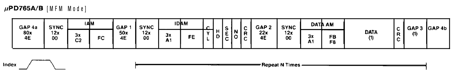
The diagnostic run should read an entire track of information allowing you to see the information including GAP#1 – GAP#4, Sync Bytes and CRCs etc.
However, on my Physical Machine the actual bits for the headers and information are bit shifted somewhat. This was consistent in the 80s and on the same machine as it is today. Could this be a controller bug? A coding error on my part or something else?
Before going in-depth, lets take a look at the code I’m using…
Read Diagnostic Code Snippet
This is the code snippet I’m using for the Diagnostic Command, which I named 35 years ago as readtrack.
;
         ORG  #9d00                     ; Alternative DDFDC Commands
         ENT  $                         ; Version 9.89 - Jason Brooks
         DI
         CALL motoron
         call trak0
         LD   hl,#100
         LD   d,0
         LD   e,0
         CALL readtrak
         CALL motoroff
         RET

readtrak
         DI
         PUSH af
         PUSH bc
         PUSH de
         PUSH hl
         LD   a,e
         LD   (drive),a
         CALL movtrak
         LD   a,e
         LD   (READ_TRACK+2),a
         LD   a,d
         LD   (READ_TRACK+3),a
         LD   de,READ_TRACK
         CALL ddfdccom
         CALL ddfdcexc
         CALL ddfdcres
         POP  hl
         POP  de
         POP  bc
         POP  af
         RET

;
;             **** DATA FOR COMMAND PHASE OF FORMAT A TRACK ****
;
READ_TRACK
         DEFB 9
         DEFB %1100010
         DEFB 0
         DEFB 0
         DEFB 0
         DEFB 1
         DEFB 6
         DEFB 1
         DEFB #52
         DEFB #ff
You’ll need the full DDFDC Code from my Primer article: https://muckypaws.com/2024/02/25/µpd765a-disc-controller-primer/ or the full code: https://github.com/muckypaws/AmstradCPC/blob/master/Assembly/DDFDC/DDFDC_MK2.asm if you don’t want to use the cutdown code earlier in the article.
When I run this on a real disk on physical hardware… The diagnostic read doesn’t provide the sector headers for the first record, just the data for the first sector found, and then continues reading the rest of the track for 8192 bytes. Since I set N = 6 (2^[7+2]).

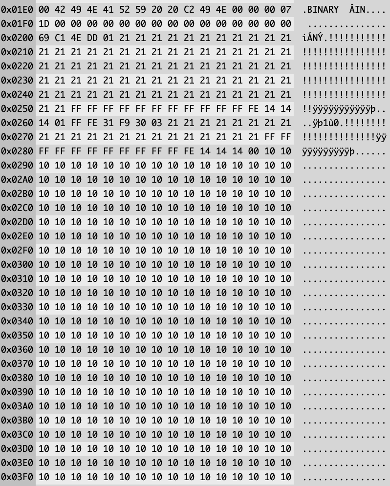
Do you see anything odd?
Directly after the DATA Block, we expect to see a CRC and GAP #3

However, we don’t, it appears that there’s some possible corruption of data. This is what I observed back in the 80’s and how I based my protection system design.
Assuming the #21 Byte is meant to be #4E, there are 77 of these instead of the 80 expected. The #FF bytes could be the SYNC Bytes, but… only 11 of these are present, basically the identifiers are corrupt… the data doesn’t appear to conform to spec.
The #10 Bytes should read as #E5, so clearly some corruption carrys on after the sector header information is processed.
Reading the individual sectors works as expected, so I know the disk is working, even after 35+ years.
GOTEK
I ran the same test on GOTEK Hardware and achieved a different result. Since GOTEK emulates the original hardware, it may be more forgiving on potential timing errors, but also will apply the FDC specification.
I’m using one of Piotr Bugaj’s amazing CPC Controllers configured as Drive B.
Running the same code except changing
         LD   hl,#100
         LD   d,0
         LD   e,0
         CALL readtrak
To set up the read on Drive B.
         LD   hl,#100
         LD   d,0
         LD   e,1
         CALL readtrak
I ran the test again with whatever disk was in that drive.

What I found interesting is the GOTEK isn’t emulating an Index Pulse that I could establish. It appeared to be reading the next sector ready to load into memory as opposed to the first after a simulated index pulse. Possible Bug in Gotek firmware? A physical drive would spin the disk until the index mark is established and then start the READ sequence.
Looking at the data after the sector, we do see data we would expect to see as a result of the diagnostic command, albeit shorter…
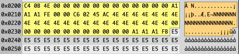
First two bytes are the Sectors CRC, a single #4E reports as GAP#3, this should be the number of bytes set when the disk was created which could be variable length.
The Spec says we expect 80 bytes of #4E for GAP#4, these are missing, followed by 12 bytes of Zero’s for SYNC Bytes which are present. The table below shows what my GOTEK simulated to the disk controller.
| ID | Bytes | Expected | Actual |
|---|---|---|---|
| CRC | 2 | Valid CRC | Valid CRC |
| GAP#3 | Variable | Multiple Bytes of #4E | One Byte |
| GAP#4A | 80 | 80 Consecutive Bytes of #4E | Not Present |
| IAM | 3 | 3 Consecutive bytes of #C2 | Not Present |
| IAM END ID | 1 | #FC | Not Present |
| GAP#1 | 50 | #4E | Not Present |
| SYNC | 12 | #00 | Present |
| IDAM | 3 | #A1 | Present |
| IDAM | 1 | #FE | Present |
| Cylinder | 1 | #00 | Present |
| Head | 1 | #00 | Present |
| Sector ID | 1 | #C6 | Present |
| Sector Size (N) | 1 | #02 | Present |
| CRC | 1 | #AC45 | Present |
| GAP #2 | 22 | #4E | Present |
| SYNC | 12 | #00 | Present |
| DATA AM | 3 | #A1 * 3 | Present |
| DATA AM | 1 | #FB | Present |
| DATA | Variable = 2^(7+N) | Sector Information | Present |
And this sequence continues throughout.

It seems that the GOTEK Adapter I have currently is almost complying with the controllers MFM Standard, but not quite.
Emulators
I ran the same test with the same code on a few Emulators I have running on macOS, WinAPE failed to execute this FDC Command, reading only the first sector.
RetroVirtualMachine however… Loads up the first sector in memory, and continues to emulate the DIAGNOSTIC COMMAND.

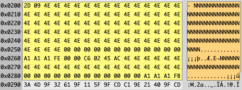
Retro Virtual Machine has added in the hidden record data from the specification as below.
| ID | Bytes | Expected | Actual |
|---|---|---|---|
| CRC | 2 | Valid CRC | Valid CRC |
| GAP#3 | Variable | Two Bytes of #4E | Two Bytes |
| GAP#4A | 80 | 80 Consecutive Bytes of #4E | Present |
| IAM | 3 | 3 Consecutive bytes of #C2 | Not Present |
| IAM END ID | 1 | #FC | Not Present |
| GAP#1 | 50 | #4E | Not Present |
| SYNC | 12 | #00 | Present |
| IDAM | 3 | #A1 | Present |
| IDAM | 1 | #FE | Present |
| Cylinder | 1 | #00 | Present |
| Head | 1 | #00 | Present |
| Sector ID | 1 | #C6 | Present |
| Sector Size (N) | 1 | #02 | Present |
| CRC | 1 | #AC45 | Present |
| GAP #2 | 22 | #4E | Present |
| SYNC | 12 | #00 | Present |
| DATA AM | 3 | #A1 * 3 | Present |
| DATA AM | 1 | #FB | Present |
| DATA | Variable = 2^(7+N) | Sector Information | Present |
Some improvement of conforming to the specification, however IAM and GAP#1 are missing. I’m giving the benefit of the doubt in respect to the GAP#3 and GAP#4a presence, assuming GAP#3 was two bytes allowing for the 80Bytes of GAP#4a
Conclusion
I want to gain further understanding into this potential issue.
- Is it a coding error on my part?
- Is there a bug in the FDC Controller?
- Is there a hardware/timing error with my particular hardware?
- What are the results on multiple machines people own?
- This is why I’m asking for your help to run this program and email me the results in for further analysis.
- Is there a Bug in the Gotek Firmware, has it been fixed in later releases?
- Am I just misunderstanding the FDC Specification?
- Which Emulators correctly implement this FDC Command?
- With a Physical Disk, run the code on a Newly Formatted Disk vs a Disk that have had files written to it.
- DATA Format disks are perfect for this test.
At the moment, more questions than answers.

