
Let’s Hack… Fly Spy!
In this post, we’re going to take a look at a Fly Spy, a game published by Mastertronic for the Amstrad CPC in 1986. The game was written by Richard Aplin, whom I recently learned was age 15 when he created this memorable masterpiece. That’s one seriously talented fella there!
In my early days as a hacker, protection systems were heavily commercialised and iterative in design. Reusing same ideas or theme as their previous incarnation, adding additional layers of obfuscation and encoding which you worked through to unlock the final secrets of code.
Speedlock, Appleby, Firebird et al, had their place and created an industry of tape to disk copiers and back up programs.
Occasionally though, you’d encounter one that was a little different… In fact, so memorable… I think of this as the equivalent of the Michelin Star award for Protection systems. Not because it was overcomplicated with faff and obfuscation. Simply because the author used tricks that hadn’t (as far as I was aware back then), been used before.
Fly Spy Loader wasn’t overly complicated, laborious or tedious as some systems were, Richard used rather elegant tricks in a bid to trip you up. I guess the difference between a sandwich and a Michelin Star Chef Club Sandwich. The ingredients are familiar and yet… Something made this stand out.
I’m going to try and explain how this protection was put together and take you through the steps of copying the original cassette to disk. Once on disk, you’re free to explore the code at will.
If the internet was available as we know it today, this would be an invaluable resource. Today with emulators and pretty much every available game cracked and archived its more reminiscing and a historical artefact.
It’s long article again, and to help I’ve created a near real-time video of the process available on my youTube channel.
Getting Started
What do you need for this tutorial?
- Amstrad CPC 6128 or earlier CPC with Extra Memory
- The extra memory will save time re-loading ADAM IDE but can be achieved on a 464.
- Emulators are perfect for this too.
- Fly Spy Cassette or original CDT Image – Google is your friend.
- Z80 Assembly Language Knowledge.
- Pencil and Paper.
- Coffee, lots of coffee or your favourite stay awake beverage!
- Mind you as a young teenager of the 80s, I coded my best hacks with the aid of beer.
- The DSK image with all the files located on my GitHub https://github.com/muckypaws/AmstradCPC
- Or click for the ZIP File below.
Let’s get started
The most important task is to make sure your Cassette or CDT Image loads correctly. Simply run the game until loading is compete and you hear the digitised words “Welcome to Fly Spy”.
Why? Well I spent half a day wondering why my code wasn’t working… Turned out it wasn’t code, but the CDT image I was using… The clue should have been the unclean loading screen 🤦🏼♂️
Also, If you have any additional ROMS enabled on your CPC or Emulator, Fly Spy will refuse to work.
For this tutorial, whilst it would be quicker with modern day toolchains… I’m retaining old school techniques, and will use (Have I mentioned this before?) ADAM, aka DAMS in Europe possibly the most underrated Assembler, Disassembler and Monitor IDE for the Amstrad CPC. Well… At least in the UK.
First Tricks…
Most commercial games you would type:-
|TAPE : ' If Disk Drive and AMSDOS is present.
RUN"
Why was Fly Spy so memorable? Simply put, and test this yourself…
Some games used a protected BASIC loader, the protection being that the code would self delete if you simply tried to load it.
Richard’s best trick was the simplest. Rewind the cassette and try this.
|TAPE : ' If Disk Drive and AMSDOS is present.
LOAD""
For every program, the first available program on cassette would LOAD, it may fail with out of memory, or self delete itself if the protected flag was set. You always ended up back at the BASIC command line.
Not Fly Spy…
Did you try this? If so you would observe the game automatically started without any further interaction from yourself. And that was not normal for the CPC, the manual is quite clear on this.
This in my mind was a very neat trick, and one I hadn’t encountered before.
Reconnaissance Phase
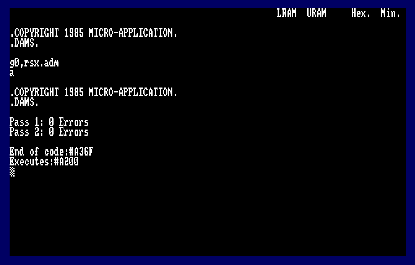
With any hack, reconnaissance is key. We’ll start ADAM and load it in an extended memory bank, we’ll also load the RSX Program created in the Dizzy tutorial.
OUT &7F00,196
RUN"ADAM
Remember CTRL+B toggles Hex Mode On/Off
Load in the RSX.ADM File and assemble as shown below. when assembled, type B at the command line to return to BASIC.
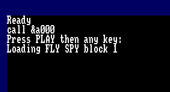
We need to know more about this cassette file. From the BASIC Command line type the following: –
CALL &A200 : ' Only do this once, don't reassemble after this.
|TAPE.IN
|FINFO

We find the information about the cassette file reported as: –
- #BF00 – Load Address
- #0001 – Length
- #0000 – Execution Address
- #03 – File Type = Protected Binary
Clearly the only true fact which can be established is the load address, the program isn’t 1 byte in length, we simply can not create a turbo loader with just one initial byte.
We need to know more…
First Stage Loader
Let’s create a very BASIC Z80 Loader :-
         ORG  #a000
start
         ENT  $
         LD   de,#1000
         LD   b,0
         CALL #BC77
         LD HL,#1000
         CALL #BC83
         JP #BC7A
We’ll specify a 2Kb Buffer for the cassette to use loading the first block at #1000, and we’ll double down and set HL to point to #1000 for the final load address. We don’t want to load code in the reserved memory space.
Did it work?

Strangely no it didn’t… If you followed along, you’ll see the familiar message “REWIND THE TAPE! Block x” message.
Why? We’ve followed the rules, we’ve opened a cassette stream, asked to load the file, we know only one block loads before the turbo loader starts… so why can’t we load this simple file?
We’ll revisit and modify our code as follows …
         ORG  #a000
start
         ENT  $
         LD   de,#1000
         LD   b,0
         CALL #BC77
         JP #BC7A
Similar to the RSX program, we only need to open the cassette header and first data block, and remember to close the stream.
We’ll run this inside ADAM.

This time round, we’ve captured some data! The Amstrad CPC typically loads the cassette header at address #B11F. The file header record is described in The Amstrad CPC Firmware guide as shown below.

| Offset | Value | Info |
|---|---|---|
| 0-15 | “FLY SPY” | Filename padded with Null Bytes (#00) |
| 16 | #02 | Block Number, usually starts with Block 1 |
| 17 | #00 | Last Block Flag, Non-Zero means we’re done. |
| 18 | #03 | File Type – 3 = Protected Binary |
| 19-20 | #0800 | Data Length = 2048 Bytes of data. |
| 21-22 | #BF00 | Load Address – Memory Address where the data is intended to be written to. |
| 23 | #01 | First Block Flag, Non-Zero means this is the first block. |
| 24-25 | #0000 | Logical Length of the file. |
| 26-27 | #0000 | Execution Address of the File |
| 28-63 | #00’s | Padding, private use |
This reveals more information to us. It’s clear that Richard has tampered with/modified the header with as much as he can get away with. The first level of obfuscation.
Cassette Header Record Info

The cassette claims the first block is “Block #02”, though the First Block Flag has to be set in order for BASIC to handle this file.
The logical length is clearly false, but we do know that #800 bytes is the data length reported inside the header, and this makes sense. The more observant of you may have noticed a quick flash of screen corruption just after the first block loaded on screen.

Clearly this isn’t corruption but program code. What’s happening…
Simply put, The BASIC cassette loader, loads the first #800 bytes (2Kb) into a buffer. When that block is complete, Firmware moves the contents of the buffer into the final destination pointed to in the cassette header.
In this case #BF00.
What’s special about #BF00? This area is reserved for the Stack Pointer. If you enter trace/monitor mode in ADAM you’ll see the Stack Pointer is currently at #BFF8. The CPC initialises the Stack Pointer to #C000 on startup.
Knowing this, have you worked out how Richard forced the program to self execute on a simple LOAD”” statement?

If you said Modified the Stack, you’d be spot on! Lets take a look at the data we’ve loaded to our buffer at memory address #1000.
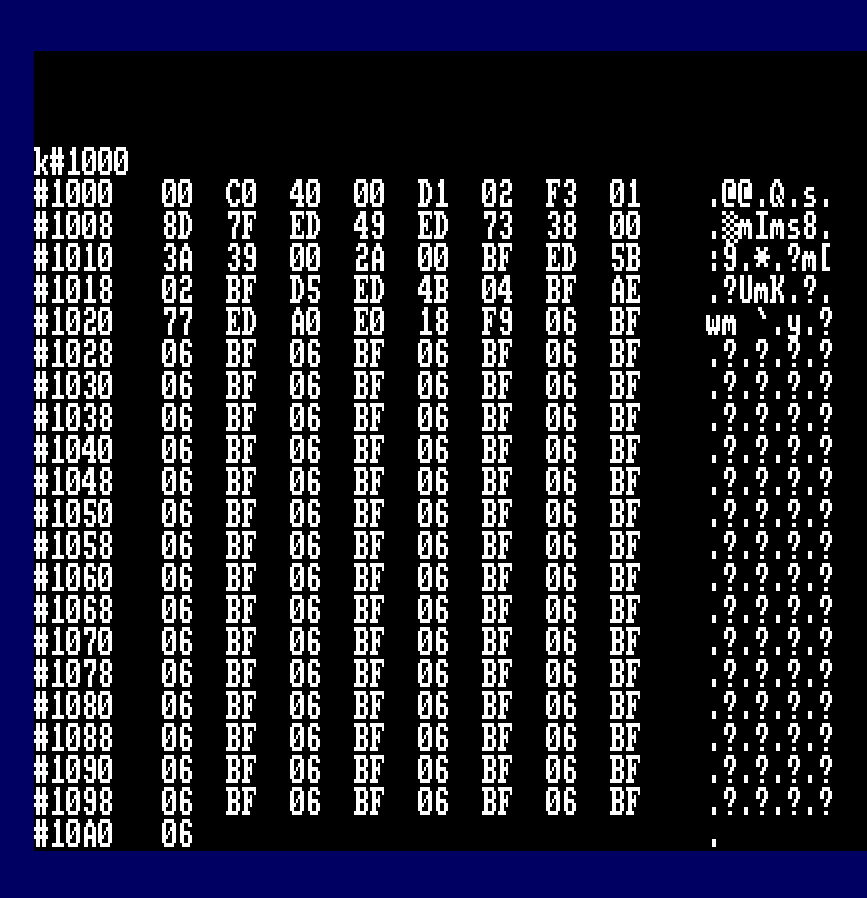
There’s a series of #06 #BF Bytes, which in little endian equals #BF06 memory address. Richard has flooded the Stack with this address. Smart move, since the stack position is largely unpredictable when a cassette load is complete. We do know it’s aligned on an even byte boundary and most likely anywhere between #BF80 – #C000
When firmware copies the data from Buffer to memory address #BF00 for #800 Bytes, data is overwritten to #BF00 through to #C6FF inclusive. At some point in the file handling firmware, a RET command will be issued and automatically resume execution at #BF06.
How smart was this move? Got to give Richard full credit for this ingenious hack, an approach that hadn’t (as far as I know been taken before his game release), and possibly enough to confuse the new assembler programmer.
Is there a workaround?
Absolutely…
We could load the original loader to the intended address by changing the location of the Stack.
         ORG  #a000
start
         ENT  $
         DI
         LD (Restore),SP
         LD SP,#a200
         LD   de,#1000
         LD   b,0
         CALL #BC77
         CALL #BC7A
         DI
         LD SP,#0000
Restore equ $-2
         RET
Temporarily reassigning the Stack Pointer removes the issue of automatically starting the loader, but … you create another issue, the rest of the code is loaded into screen memory meaning you will need to preserve that. It’s doable, it’s a faff but there’s a smarter way…
Disassembling the Loader
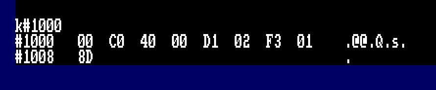
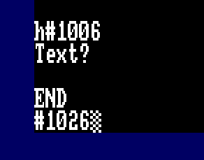
For this point, we’re going to be talking about offsets in the code. We’ve loaded the initial code to memory address #1000, which should have been #BF00. We know execution begins at #BF06, so we need to examine code at…. #1006. That’s right, an offset of 6 bytes into the temporary load location.

#1006   DI                  F3
#1007   LD   BC,#7F8D       018D7F
#100A   OUT  (C),C          ED49
#100C   LD   (#38),SP       ED733800
#1010   LD   A,(#39)        3A3900
#1013   LD   HL,(#BF00)     2A00BF
#1016   LD   DE,(#BF02)     ED5B02BF
#101A   PUSH DE             D5
#101B   LD   BC,(#BF04)     ED4B04BF
#101F   XOR  (HL)           AE
#1020   LD   (HL),A         77
#1021   LDI                 EDA0
#1023   RET  PO             E0
#1024   JR   #101F          18F9
#1026   LD   B,#BF          06BF
This code is fairly straight forward, the basic and smallest amount of code to ensure the stack trick works. Fly Spy needs to ensure the stack trick worked meaning minimalist code at the start of #BF00
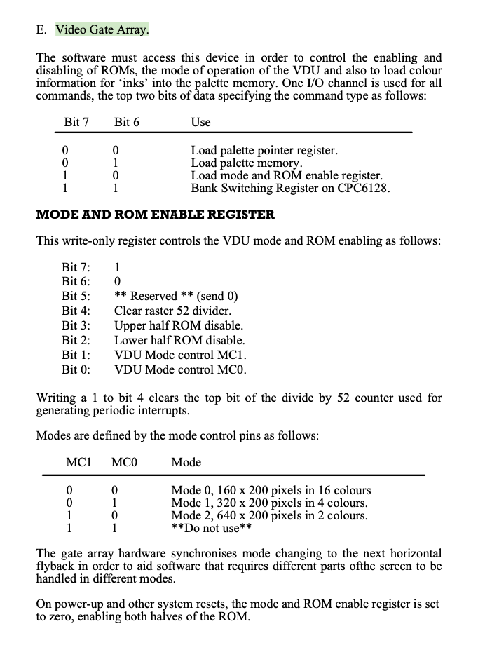
Since the code was executed from firmware not completing its call, the Upper and/or Lower ROM could still be enabled, a Write to the Video Gate Array Disables the Upper and Lower ROMS and set the screen to MODE 1 in a single write instruction. Setting Bit 7, Bit 3 (Upper ROM Disable), Bit 2 (Lower ROM Disable) and Bit 0 (MC0) is the key.
LD   BC,#7F8D
OUT  (C),C
Extract of the Video Gate Array #7F
Another Stack Trick
Next up is the first Decode routine. Most protection systems included this as part of their obfuscation, albeit a pretty pointless exercise.
Memory address #38 is pretty important, it’s the RST 7 instruction, also the fast ticker event queue. If you modify this with random data you’re likely to crash the machine.
Richard stores the current stack pointer location at address #38, this is to prevent any copier program using Fast Ticker events to intercept code and ensure interrupts remain disabled. He then primes the accumulator with the High Byte Value of the Stack Pointer, this will be #BF if you haven’t changed the stack to another memory address.
#100C   LD   (#38),SP       ED733800
#1010   LD   A,(#39)        3A3900
#1013   LD   HL,(#BF00)     2A00BF
#1016   LD   DE,(#BF02)     ED5B02BF
#101A   PUSH DE             D5
#101B   LD   BC,(#BF04)     ED4B04BF
#101F   XOR  (HL)           AE
#1020   LD   (HL),A         77
#1021   LDI                 EDA0
#1023   RET  PO             E0
#1024   JR   #101F          18F9
#1026   LD   B,#BF          06BF
Next up, Richard initialises HL, DE and BC with the contents of memory address #BF00, which is essentially a table.
Reading the code we know the following to be true.
- HL = #C000
- DE = #0040
- BC = #02D1
- A = #BF
A short loop will read the bytes from screen memory, XOR with the contents of A and write it to memory address #40 for #2D1 bytes.
The next section of code is executed at address #40. Remember the Speedlock trick of Pushing the return address on the stack?
Interestingly, Richard didn’t add the Refresh Register R into the mix, this would have made it more interesting.
Decode the next stage
To decode the next stage, we could easily type in the assembler needed… or, we could use a simple ADAM trick to convert disassembly into source code.
Modifying the program we created to load the loader, go back to the editor and make the following changes, also ensure the program editor cursor is set to the very last line.


The beauty of ADAM here is that it recognises any Jump Relative and other commands, AND… if the memory address is in range of the source code requested will generate a label for you. Here we can see the Jump Relative command looping back to R101F.
We’ll modify this to account for the changes we made to the load location. Remember what I said about offsets? HL = #C000, clearly we’re not loading the code there, but instead from #1100.
Why #1100?
#C000 – #BF00 = #100, we loaded the code to #1000, so the offset it #100. #1000 + #100 = #1100.
I made the following changes to the source.
decode
;
         DI
         LD   BC,#7F8D
         OUT  (C),C
         LD   A,#BF
         LD   HL,#1000
         LD   DE,(#1002)
         LD   BC,(#1004)
R101F    XOR  (HL)
         LD   (HL),A
         LDI
         RET  PO
         JR   R101F
;
If you have the patience, you can trace this routine to completion, that would be 721 iterations. Or… we can just skip all that, assemble the code and within ADAM, use:-
A
Jdecode
The next stage loader code has been revealed.
Next Stage Loader Code
The loader code has been decoded and if you disassemble code from #40 you’ll see this code snippet.
#  40   DI                  F3				; Disable Interrupts
#  41   LD   BC,#7F8D       018D7F
#  44   OUT  (C),C          ED49			; Switch off Upper/Lower ROM and Set MODE 1
#  46   LD   HL,#310        211003			; HL = #310
;
; Basically a routine to wipe all memory from #310 through to #FFFF
; and loopback round to #0000 - #003F
;
Loop1
#  49   LD   (HL),#00       3600			; POKE (HL),0
#  4B   INC  HL             23				; HL = HL + 1
#  4C   LD   A,H            7C				; A = H
#  4D   OR   A              B7				; Is H = 0?
#  4E   JR   NZ,#49         20F9			; If not back to Loop1
#  50   LD   A,L            7D				; Check L
#  51   CP   #3F            FE3F			; L = #3F? Basically checking if HL = #003F
#  53   JR   NZ,#49         20F4			; Back to Loop 1 if not.
#  55   IM   1              ED56			; Set Interrupt Mode 1
#  57   JR   #70            1817			; Continue execution
And frankly, we don’t need this, it’s Richards way of erasing all memory from #310 looping through to #003F. Firmware, BASIC Data and any intercept code you may have introduced is erased, there’s no timing requirements on the R Register, this makes it easier. We will simply ignore this code as it’s designed to thwart our efforts and not required.
CRTC Register Initialisation
Control continues from address #70 which initialises the CRTC Registers. It’s unclear why Richard has done this as he doesn’t really deviate from the standard on startup.
The routine basically loops around, reading data from memory address #5B and writing to each CRTC Register. #BCxx is the control/command, #BDxx is the data.
;
; Initialise the CRTC Registers
;
#  70   LD   BC,#BC00       0100BC			; CRTC Register
#  73   LD   HL,#5B         215B00			; Point HL to a DATA Block
#  76   OUT  (C),C          ED49			; Write to CRTC Command Register
#  78   INC  B              04				; Set to Data Register #BDxx
#  79   LD   A,(HL)         7E				; Get data from Table
#  7A   OUT  (C),A          ED79			; Write to the CRTC Data Register
#  7C   DEC  B              05				; Set to Command Register #BCxx
#  7D   INC  C              0C				; C = C + 1
#  7E   LD   A,C            79				; A = C
#  7F   INC  HL             23				; HL = HL + 1 (Point to next data in table)
#  80   CP   #10            FE10			; Have we written 16 registers?
#  82   JR   NZ,#76         20F2			; If not loop back

;
; Data Held at Address #5B
;
    ORG #5B
    DEFB #3F, #28, #2E, #8E, #26, #00, #19, #1E
    DEFB #00, #07, #00, #00, #30, #00, #00, #00
;
; or as disassembly...
;
#  5B   CCF                 3F
#  5C   JR   Z,#8C          282E
#  5E   ADC  A,(HL)         8E
#  5F   LD   H,#00          2600
#  61   ADD  HL,DE          19
#  62   LD   E,#00          1E00
#  64   RLCA                07
#  65   NOP                 00
#  66   NOP                 00
#  67   JR   NC,#69         3000
#  69   NOP                 00
#  6A   NOP                 00
If you look at the data being sent to each Register in turn, the code initialises the default values for all registers…. except Start Address H – Register 12. This suggests an address of #3000 to render the screen, but it never happens…
CRTC Register Info from Soft 968

Palette Initialisation
Once the CRTC has been initialised, the code sets the colour palette directly to the Video Gate Array, with the code below. There is a bug however. When writing a new hardware colour to the Video Gate Array, you first set the register you wish to change, and then set Bit 6 with the new hardware colour value when the write command is executed.
Border is #7F10, but the value #14 was written and NOT #54 which would have worked. It’s unclear why he explicitly set Bit 6 with the OR #40 command instead of adjusting the table.
#  84   LD   HL,#6B         216B00			; Memory Address for Hardware Colour Palette
#  87   CALL #8C            CD8C00			; Initialise the colour Palette

;
; Hardware Palette Initialisation
;
#  8C   LD   BC,#7F10       01107F			; Video Gate Array, #7F10 = Border Colour
#  8F   OUT  (C),C          ED49			; Request Write to Border Colour Palette
#  91   LD   A,(HL)         7E				; Get Data from Table = #14
#  92   OUT  (C),A          ED79			; Write new Hardware Colour to Register
;
; This was bugged, the value used was #14 in the table, this could not be written
; Bit 6 must be set to write the value.  It was probably ignored since the border
; will flash when loading the code anyway.
;
#  94   LD   C,#00          0E00			; Set C = 0, we're going to write from #7F00 to #7F03
#  96   INC  HL             23				; HL = HL + 1, next colour entry in table
#  97   OUT  (C),C          ED49			; Prime Palette Register
#  99   INC  C              0C				; C = C + 1, Point to Next Colour Register
#  9A   LD   A,(HL)         7E				; Get Colour From Table
#  9B   OR   #40            F640			; Set Bit 6 to Write the Value
#  9D   OUT  (C),A          ED79			; Set the new Colour Value.
#  9F   INC  HL             23				; HL = HL + 1, []
#  A0   LD   A,C            79				; Check if we've written four colours
#  A1   CP   #04            FE04            ; Compare to maximum colours for MODE 1
#  A3   JR   NZ,#97         20F2 			; Loop back if not
#  A5   RET                 C90				; Hardware Colour Palette set.

;
; Colour Table
;
ORG #6B
DEFB #14, #14, #17, #04, #15
;
; Hardware Colour Table
;
#  6B   INC  D              14				; 0  - Black Border
#  6C   INC  D              14				; 0  - Ink 0 Black
#  6D   RLA                 17				; 11 - Ink 1 Sky Blue
#  6E   INC  B              04				; 1  - Ink 2 Blue
#  6F   DEC  D              15				; 2  - Ink 3 Bright Blue
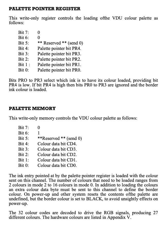
Hardware Colours?
What’s this all about? Typically the Amstrad CPC we’d set the colours/palette either in BASIC using commands like INK 1,26 to set INK 1 to White, or using calls to firmware routine at #BC32, these all hide the hardware implementation which ultimately set the Video Gate Array registers accordingly. To make matters more interesting, the Hardware Colours don’t match software colour table you might see on your CPC.

You can either write down a table of hardware colour values for reference, or do what I did back in the day, be lazy and write a BASIC program to decode them for me.
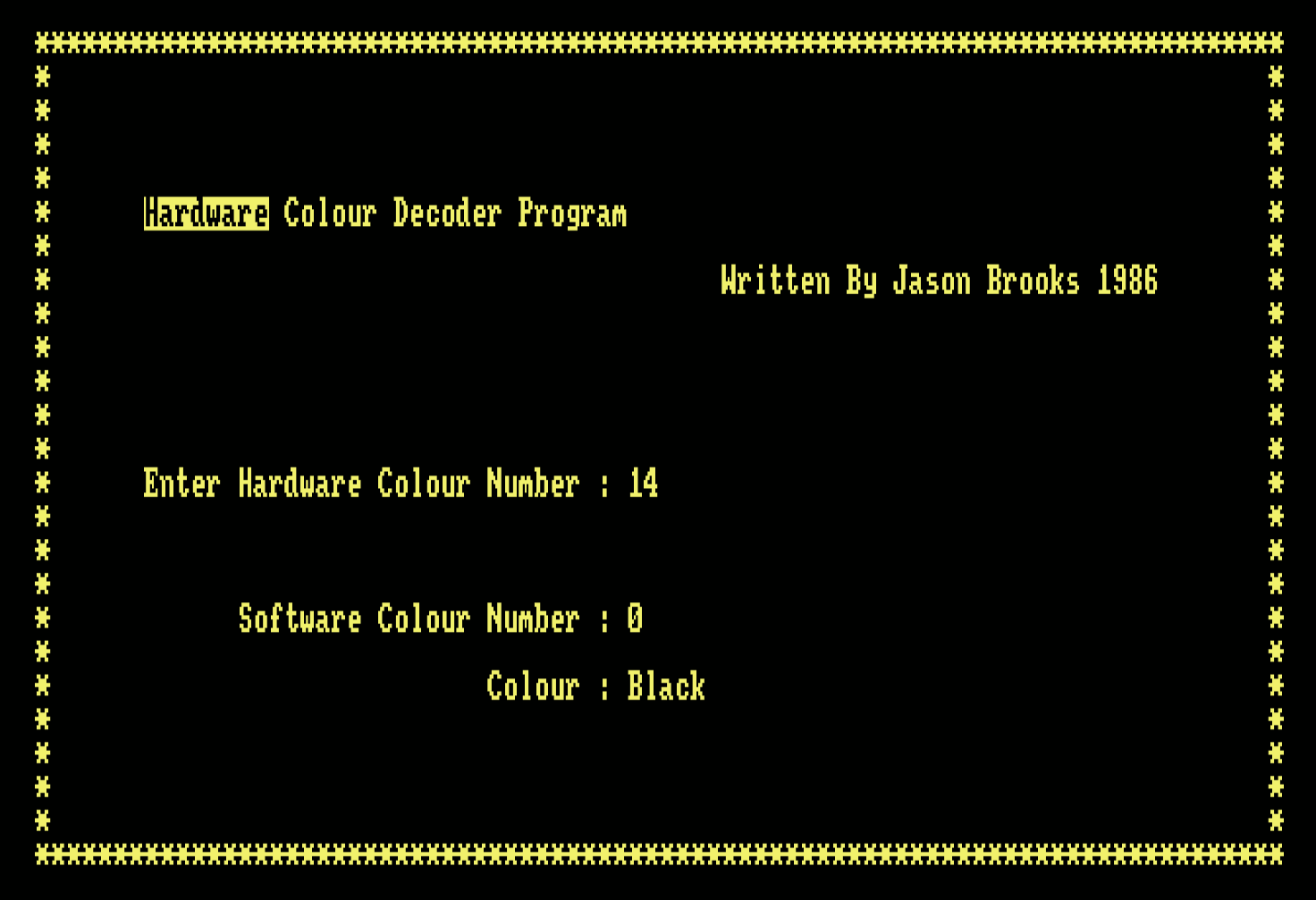
Hardware Colour Decoder Program – Listing
10 ' Written By J.Brooks '86
20 RESTORE:CLEAR
30 CALL &BBFF:CALL &BC02:BORDER 0:INK 0,0:INK 1,25:PAPER 0:PEN 1:MODE 2
40 t$="DH":PRINT "Are You Entering Numbers In ėHėex Or ėDėec ? "
50 a$=UPPER$(INKEY$):IF a$="" THEN 50
60 t=INSTR("DH",a$):IF t=0 THEN 50
70 FOR i=1 TO 80:LOCATE i,1:PRINT"*";:LOCATE 81-i,25:PRINT"*";:NEXT
80 FOR i=2 TO 24:LOCATE 80,i:PRINT"*";:LOCATE 1,26-i:PRINT"*";:NEXT
90 LOCATE 8,6:PRINT"ėHardwareė Colour Decoder Program"
100 LOCATE 45,8:PRINT"Written By Jason Brooks 1986"
110 ' Initialize
120 DIM hardware(40),hardware$(40),ha$(40)
130 template$="ABCDEF0123456789":IF t=1 THEN template$=RIGHT$(template$,10)
140 FOR i=0 TO 26:hardware(i)=255:hardware$(i)="Un-Defined Colour !":NEXT
150 FOR i=0 TO 26:READ a,a$:hardware(a)=i:hardware$(a)=a$:NEXT
160 ' Get Keynumbers & Display Actual Key
170 LOCATE 8,14:PRINT"Enter Hardware Colour Number : "
180 LOCATE 14,18:PRINT"Software Colour Number : "
190 LOCATE 30,20:PRINT"Colour : "
200 ' Get Key Presses
210 x=0:b$=""
220 WHILE x<>2
230 a$=UPPER$(INKEY$):IF a$="" THEN 230 ELSE IF INSTR(template$,a$)=0 THEN 230
240 x=x+1:IF x=1 THEN LOCATE 39,14:PRINT"  "
250 LOCATE 38+x,14:PRINT a$:b$=b$+a$
260 WEND
270 IF t=1 THEN ke=VAL(b$) ELSE ke=VAL("&"+b$)
280 LOCATE 38,18:PRINT SPACE$(20):LOCATE 38,20:PRINT SPACE$(30):LOCATE 38,18
290 IF ke>31 THEN ke=ke XOR &40:IF ke>31 THEN 320
300 IF hardware(ke)=255 THEN PRINT" Un-Defined" ELSE PRINT hardware(ke)
310 LOCATE 39,20:PRINT hardware$(ke)
320 GOTO 200
330 ' Hardware Ink Values & Hardware Ink Names
340 DATA 20,Black,4,Blue,21,Bright Blue,28,Red,24,Magenta,29,Mauve
350 DATA 12,Bright Red,5,Purple,13,Bright Magenta,22,Green,6,Cyan,23,Sky Blue
360 DATA 30,Yellow,0,White,31,Pastel Blue,14,Orange,7,Pink,15,Pastel Magenta
370 DATA 18,Bright Green,2,Sea Green,19,Bright Cyan,26,Lime,25,Pastel Green
380 DATA 27,Pastel Cyan,10,Bright Yellow,3,Pastel Yellow,11,Bright White
Final Pre-Flight Checks
Ok, where were we? Ah yes… We’ve looked at wiping memory, initialised the CRTC, Set the Screen Mode what’s next?
The code performs a Jump Relative to address #A6.
At address #A6, Richard calls a routine to check for any external ROMs installed on the system. If any are found that are not BASIC or AMSDOS, the program terminates by calling kill code to erase everything in memory.
Before we go into the code, there are two ports that need to be queried.
- #7F,#85 Sets Screen Mode 1 and enables Upper ROM
- #DF,x selects upper rom 0-255
- #7F,#8D Sets Screen Mode 1 and disables Upper and Lower ROMS.
When an upper ROM is selected, the program resides at address #C000 (Screen memory). The CPC thankfully only renders the display from RAM.
Richard Checks for the presence of BASIC and if the ROM is a Background ROM. The code checks if the background ROM is AMSDOS. Anything else, will result in Kill Code being executed. Richard Really doesn’t want anything but a BASIC Barebones Amstrad Running…
ROM Format
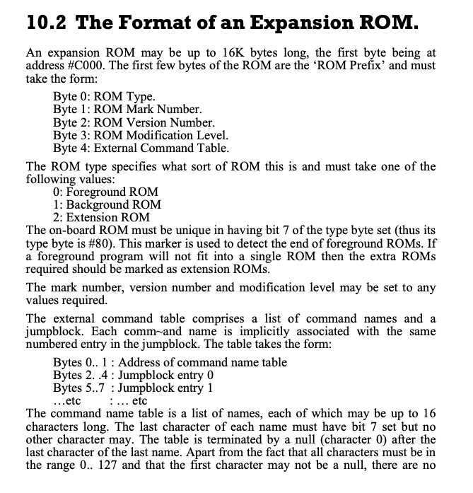
Pre-Flight Source Code
The final section of code for the loader.
Clearly we don’t need the call to #F0, this checks for external ROMS, or other devices like Hackit or Multiface etc. And a few times writing this, I tripped up as I like to enable UTOPIA ROM for some file commands.
AMSDOS is hardwired as ROM7, this is a background rom, #C000 = 01, and #C073 = #50

;
; Final Pre-Flight Checks and Game Loader Code.
;
#  A6   CALL #F0            CDF000			; Check if any ROMS are loaded
#  A9   LD   SP,#30F        310F03			; Set the Stack to below code load
#  AC   LD   IX,#310        DD211003		; Load Address Start
#  B0   LD   DE,#3FFF       11FF3F			; Number of Bytes to Load
#  B3   CALL #11F           CD1F01			; Load #3FFF Bytes to #310 Turbo Styleee
#  B6   LD   HL,#310        211003
#  B9   LD   DE,#C000       1100C0
#  BC   LD   BC,#3FFC       01FC3F			; Display the Loading Screen
#  BF   LDIR                EDB0			; Copy the data in memory #310 to Screen
#  C1   LD   IX,#310        DD211003		; Set Load Address
#  C5   LD   DE,#5000       110050			; Load #5000 Bytes to #310
#  C8   CALL #11F           CD1F01			; Load the Code from Cassette
#  CB   LD   DE,#6950       115069			; IX = #5310, Request another #6950 Bytes
#  CE   CALL #11F           CD1F01			; Load More Code
#  D1   LD   SP,#FFFF       31FFFF			; IX = #BC60, Reset Stack to Top of Screen memory
#  D4   LD   HL,#EB         21EB00			; Send some more code to Screen
#  D7   LD   DE,#C7D1       11D1C7
#  DA   PUSH DE             D5				; Execution will continue from #C7D1
#  DB   LD   BC,#05         010500			; Copying Five Bytes from #EB
#  DE   LDIR                EDB0			; Copy Data to Screen
#  E0   LD   HL,#310        211003			; Initialise the Registers
#  E3   LD   DE,#100        110001			; To Shift the entire code
#  E6   LD   BC,#B950       0150B9			; to the final location for #B950 bytes
#  E9   DI                  F3				; Make Sure Interrupts are disabled.
#  EA   RET                 C9				; Return - Will Jump to #C7D1 which will execute
											; The two instructions below
;
; Code to copy to the screen.
;
#  EB   LDIR                EDB0
#  ED   JP   #7756          C35677
;
; Check if any Non-Standard ROMS are installed.
;
#  F0   LD   BC,#7F00       01007F			; Video Gate Array - Does more than video
#  F3   LD   C,#85          0E85			; Switch Upper ROM on, retaining MODE 1
#  F5   OUT  (C),C          ED49			; Enable Upper ROM
#  F7   LD   B,#DF          06DF			; #DFxx is Expansion Rom Select
#  F9   LD   C,#00          0E00			; C = ROM 0
#  FB   OUT  (C),C          ED49			; Switch ROM 0 in
#  FD   LD   A,(#C000)      3A00C0			; Get Byte from ROM
# 100   BIT  7,A            CB7F			; Bit 7 Set?  CPC BASIC ROM
# 102   JR   NZ,#113        200F			; BASIC ROM Found goto #113
# 104   CP   #02            FE02			; Check ROM Type
# 106   JR   Z,#11C         2814			; If Extension ROM, Kill the program.
# 108   CP   #01            FE01			; Check if Background ROM
# 10A   JR   NZ,#11C        2010			; If not Background ROM, Kill the Program.
# 10C   LD   A,(#C073)      3A73C0			; Looking for AMSDOS, Specific Byte
# 10F   CP   #50            FE50			; If Not AMSDOS, Kill the program
# 111   JR   NZ,#11C        2009			;
# 113   INC  C              0C				; C = C + 1, look for next External ROM
# 114   JR   NZ,#FB         20E5			; Loop for 255 possible ROM Addresses.
# 116   LD   BC,#7F8D       018D7F			; Switch Upper ROM off
# 119   OUT  (C),C          ED49
# 11B   RET                 C9				; Check Complete, no extra ROMS detected.
# 11C   JP   #133           C33301			; Kill Code routine.

;
; Kill Code - Erase Memory, though the LDIR will stop at address #13F
; leaving three bytes, to loop infinitely.
;
# 133   LD   HL,#143        214301			; Point HL to #143
# 136   LD   (HL),#00       3600			; POKE (#143),#00
# 138   LD   DE,#144        114401			; Set DE to #144
# 13B   LD   BC,#FFFF       01FFFF			; BC Counter to maximum 65535
# 13E   DI                  F3				; Disable Interrupts
# 13F   LDIR                EDB0			; Copy 00 byte to all addresses
# 141   JR   #141           18FE			; Lock the Processor, infinite loop
Post checking no additional ROMs are installed, the game finally hits the loading stage!
The Loader
Now we’ve completed initialisation and pre-flight checks, the code now focus’ on the loader.
#  AC   LD   IX,#310        DD211003		; Load Address Start
#  B0   LD   DE,#3FFF       11FF3F			; Number of Bytes to Load
#  B3   CALL #11F           CD1F01			; Load #3FFF Bytes to #310 Turbo Styleee
#  B6   LD   HL,#310        211003
#  B9   LD   DE,#C000       1100C0
#  BC   LD   BC,#3FFC       01FC3F			; Display the Loading Screen
#  BF   LDIR                EDB0			; Copy the data in memory #310 to Screen
#  C1   LD   IX,#310        DD211003		; Set Load Address
#  C5   LD   DE,#5000       110050			; Load #5000 Bytes to #310
#  C8   CALL #11F           CD1F01			; Load the Code from Cassette
#  CB   LD   DE,#6950       115069			; IX = #5310, Request another #6950 Bytes
#  CE   CALL #11F           CD1F01			; Load More Code
We basically have three sections of code to load
- The Title Screen
- Initially loaded at #310
- When complete, copied to the screen.
- Game Code Part 1
- Loaded at #310 for #5000 Bytes
- Game Code Part 2
- Loaded at #5310 for #6950 Bytes
The call to #11F is essentially the load data from cassette routine. It will :-
- Switch Cassette Motor Relay On
- Load data from cassette for DE number of Bytes to Address in IX
- Switch Cassette Motor Relay Off
- IX = Next Address to Load Data
- Check if DE = #0000
- If DE is any other value, there was a problem loading data, so time to kill to whole program.
- In fact the loader code has to work pretty hard not to be killed… Any fans of Snatch will know the reference.
Tape Loader Code Snippet
;
; Cassette Motor Control and Load Routine
;
# 11F   LD   B,#F6          06F6			; µPD8255 Port C Data Port
# 121   LD   A,#10          3E10			; Enable the Cassette Motor Relay
# 123   OUT  (C),A          ED79			; Switch the Relay On
# 125   LD   A,#FF          3EFF			; Initial Value
# 127   SCF                 37				; Set Carry Flag
# 128   CALL #143           CD4301			; Load Data from Cassette
# 12B   LD   B,#F6          06F6			; Disable the Cassette Motor
# 12D   XOR  A              AF				;
# 12E   OUT  (C),A          ED79			; Switch the Motor Relay Off
# 130   LD   A,D            7A				; Check add expected data loaded
# 131   OR   E              B3				; Does DE = #0000?
# 132   RET  Z              C8				; If so, return otherwise... Kill Code Time.
;
; Kill Code - Erase Memory, though the LDIR will stop at address #13F
; leaving three bytes, that loop infinitely.
;
# 133   LD   HL,#143        214301			; Point HL to #143
# 136   LD   (HL),#00       3600			; POKE (#143),#00
# 138   LD   DE,#144        114401			; Set DE to #144
# 13B   LD   BC,#FFFF       01FFFF			; BC Counter to maximum 65535
# 13E   DI                  F3				; Disable Interrupts
# 13F   LDIR                EDB0			; Copy 00 byte to all addresses
# 141   JR   #141           18FE			; Lock the Processor, infinite loop
The tape loader code no longer contains further traps, we can relax.
The Preparation
We’re at the stage now where we’ve decoded the actual loader and look at how we transfer this to disk.
The first two pieces of code are straight forward, they load into memory in easily accessible addresses that doesn’t interfere with the Amstrad Operating System.
The final piece of code, which loads at #5310 for #6950 bytes, presents a challenge. Data will be loaded upto #BC60. That would banjax our ability to access the disk without corrupting the game data.
My approach, is straight forward…
- Load the Title Page at address #310
- Copy the Screen to the correct memory location #C000
- Write the Disk File FLYSPY1.BIN
- Load the First Part Game code to #310
- Write the Disk File FLYSPY2.BIN
- Load the Second Part Game code to #1000
- Write a Disk File from #1000 for #5000 Bytes. FLYSPY3.BIN
- Write a Disk File from #6000 for #1950 Bytes. FLYSPY4.BIN
Copying the game code into four separate files.
Because we loaded game code over itself and corrupted the first part, there’s nothing more to do than reset the Amstrad with an RST #0
Create the Transfer Code
The section of transfer code looks like below, you’ll spot a generic SAVE routine I’ve used elsewhere, given the information we know about the Fly Spy system, you can shave a few bytes off the code for parts that don’t need executing or irrelevant. I’ve highlighted some examples for you, but… can you optimise it further? I’m fairly sure you can!
;
; Our intercept Routine
;
next
         DI   					; Switch off interrupts again (Probably not needed)
         LD   bc,#7fc0
         OUT  (c),c				; Make sure ADAM Is switched out
;
         LD   IX,#310
         LD   DE,#3FFF
         CALL #11F				; Load the Title Page from Cassette
         LD   HL,#310
         LD   DE,#C000
         LD   BC,#3FFC			; We're going to copy the data to screen
         PUSH de				; Store the Destination Address
         PUSH bc				; Store the Length
         LDIR 					; Copy data to screen
         POP  de				; DE = Data Length to Save
         POP  ix				; IX = Memory Location of Data to Save from
         LD   bc,0				; Execution Address = 0
         CALL save				; Save out first file.
;
         LD   IX,#310
         LD   DE,#5000			; Prime IX with Load Address and DE with Length
         PUSH ix
         PUSH de				; Preserve on Stack Saves setting them again.
         CALL #11F				; Load next file from Cassette
         POP  de
         POP  ix				; Restore IX = Save Address, DE = Length
         CALL save				; Save out Second Game file.
         LD   ix,#1000
         LD   de,#6950			; Prime IX with Load Address and DE with Length
         PUSH ix
         PUSH de				; Preserve on Stack Saves setting them again.
         CALL #11F				; Load final file from Cassette
         POP  de
         POP  ix				; Restore IX = Save Address, DE = Length
         LD   de,#5000			; Set DE for Length #5000
         CALL save				; Save File Number 3
         LD   ix,#6000			; Set IX and DE for final section of code
         LD   de,#1950
         CALL save				; Save Final File number 4
         RST  0					; Reset the Amstrad
;
; Save routine, for Fly Spy.
; IX = Memory Address to Save data from
; DE = Length of data to save
; BC = Execution Address
;
; Note the filename will increment the number on each call.
;
save
         DI   					; Disable Interrupts
         LD   bc,#f600			; We're going to send a signal to the PD8255 Device
         OUT  (c),c				; Switch Cassette Motor Relay Off
         LD   hl,fname+6		; Point to place in filename that contains the digit
         INC  (hl)				; Increment the filenumber, i.e 0 -> 1, 1 -> 2 etc
         LD   hl,fname			; Point to the Filename
         PUSH bc
         PUSH de
         PUSH ix				; Preserve the data passed
         LD   b,fnamel			; B = Length of Filename
         LD   de,#c000			; Temporary Buffer address
         CALL #bc8c				; Open file for Write
         POP  hl				; HL = Address of Data to Write
         POP  de				; DE = Length of Data to Write
         POP  bc				; BC = Execution Address
         LD   a,2				; A = Filetype, 2 = Binary
         CALL #bc98				; Write the File
         CALL #bc8f				; Close the Filestream
         DI   					; Disable interrupts again
         LD   bc,#f610			; We're going to switch the cassette motor back on
         OUT  (c),c				; Cassette Motor On
         RET  					; Complete.
fname    DEFM FLYSPY0.BIN		; Filename
fnamel   EQU  $-fname			; Calculate the Filename Length
Running the Transfer
If you’re not using ADAM but an inbuilt emulator’s assembler, Maxam or other tooling, it’s worth noting that Double Quotes are typically required for DEFM statements. ADAM optimised memory utilisation by not requiring them, though I’m aware it causes challenges with other tools.
Assemble the final full transfer code, exit ADAM and from BASIC type.
|TAPE.IN
|DISC.OUT
CALL &BE80
Remember it’s important to ensure that TAPE is set for input and DISC for output otherwise it won’t work.
Full Transfer Code
The final Tape to Disc Transfer Code is included below. Did you see an error in ADAM when trying to assemble it?
You will need to modify ADAM to allow assembly at higher address ranges. Assuming you have loaded ADAM at #4000, return to BASIC and type the following: –
POKE &4051,255
CALL &4000
;
; FlySpy - Tape to Disk Copier - Jason Brooks
; Version for my Blog at www.muckypaws.com
; also check out my merch at www.muckypawslabs.com
;
; Before running, use the following commands in BASIC
;	|TAPE.IN : |DISC.OUT
;
         ORG  #be80				; We'll keep it high!
start
         ENT  $					; Start of Execution
         DI   					; Disable Interrupts
         LD   bc,#7fc0
         OUT  (c),c				; Switch in Main Memory - Protect ADAM
         LD   de,#1000			; Temporary Buffer
         LD   b,0				; Filelength of 0 - First file found
         CALL #bc77				; Open Cassette for Input
         CALL #bc7a				; Close the Cassette Stream
;
; Fly Spys Decoding Routine Modified
;
firstxor
;
         DI   					; Disable interrupts again as Firmware calls will
         						; reenable them
         LD   hl,next			; Point to our Intercept Code
         PUSH hl				; Push this to Stack to ensure safe return.
         LD   BC,#7F8D
         OUT  (C),C				; Switch off Upper/Lower ROMS
         LD   A,#bf				; initialise A with seed value.
         LD   HL,#1100			; Our code is at #1100 now
         LD   DE,(#1002)		; Get Destination from FlySpy Table
         LD   BC,(#1004)		; Get Length from Fly Spy Table
R101F    XOR  (HL)				; XOR The byte with value in A
         LD   (HL),A			; Write back to memory
         LDI  					; Copy Byte from HL to DE and Decrease BC
         RET  PO				; If BC = 0 then Quitting time!
         JR   R101F				; Loop until complete.
;
; Our intercept Routine
;
next
         DI   					; Switch off interrupts again (Probably not needed)
         LD   bc,#7fc0
         OUT  (c),c				; Make sure ADAM Is switched out
;
         LD   IX,#310
         LD   DE,#3FFF
         CALL #11F				; Load the Title Page from Cassette
         LD   HL,#310
         LD   DE,#C000
         LD   BC,#3FFC			; We're going to copy the data to screen
         PUSH de				; Store the Destination Address
         PUSH bc				; Store the Length
         LDIR 					; Copy data to screen
         POP  de				; DE = Data Length to Save
         POP  ix				; IX = Memory Location of Data to Save from
         LD   bc,0				; Execution Address = 0
         CALL save				; Save out first file.
;
         LD   IX,#310
         LD   DE,#5000			; Prime IX with Load Address and DE with Length
         PUSH ix
         PUSH de				; Preserve on Stack Saves setting them again.
         CALL #11F				; Load next file from Cassette
         POP  de
         POP  ix				; Restore IX = Save Address, DE = Length
         CALL save				; Save out Second Game file.
         LD   ix,#1000
         LD   de,#6950			; Prime IX with Load Address and DE with Length
         PUSH ix
         PUSH de				; Preserve on Stack Saves setting them again.
         CALL #11F				; Load final file from Cassette
         POP  de
         POP  ix				; Restore IX = Save Address, DE = Length
         LD   de,#5000			; Set DE for Length #5000
         CALL save				; Save File Number 3
         LD   ix,#6000			; Set IX and DE for final section of code
         LD   de,#1950
         CALL save				; Save Final File number 4
         RST  0					; Reset the Amstrad
;
; Save routine, for Fly Spy.
; IX = Memory Address to Save data from
; DE = Length of data to save
; BC = Execution Address
;
; Note the filename will increment the number on each call.
;
save
         DI   					; Disable Interrupts
         LD   bc,#f600			; We're going to send a signal to the PD8255 Device
         OUT  (c),c				; Switch Cassette Motor Relay Off
         LD   hl,fname+6		; Point to place in filename that contains the digit
         INC  (hl)				; Increment the filenumber, i.e 0 -> 1, 1 -> 2 etc
         LD   hl,fname			; Point to the Filename
         PUSH bc
         PUSH de
         PUSH ix				; Preserve the data passed
         LD   b,fnamel			; B = Length of Filename
         LD   de,#c000			; Temporary Buffer address
         CALL #bc8c				; Open file for Write
         POP  hl				; HL = Address of Data to Write
         POP  de				; DE = Length of Data to Write
         POP  bc				; BC = Execution Address
         LD   a,2				; A = Filetype, 2 = Binary
         CALL #bc98				; Write the File
         CALL #bc8f				; Close the Filestream
         DI   					; Disable interrupts again
         LD   bc,#f610			; We're going to switch the cassette motor back on
         OUT  (c),c				; Cassette Motor On
         RET  					; Complete.
fname    DEFM FLYSPY0.BIN		; Filename
fnamel   EQU  $-fname			; Calculate the Filename Length
Creating a New Loader
Congratulations! You’ve now hacked the Loader and transferred the game to disk. How easy was that? What’s left? The last and final step is to create a loader to start and play the game.
This is easy to produce, we repeat the steps used when saving the game with an exception.
The final piece of game code.
Remember we split that final file into two, we have to put that back to the original memory location. To achieve this, we’ll load the final code to screen and copy this back to the original location. A common trick we used back then for CPCs with 64Kb memory. Of course if you’re running on an expanded memory machine, you can modify the loader to load the final data block into expanded memory instead.
Can you modify the code to do this?
Hint: LD BC,#7FC5:OUT (C),C and LD BC,#7FC0:OUT(C),C
;
; Fly Spy Loader - for the www.muckypaws.com Blog
;
; Jason Brooks
;
         ORG  #be80					; Typical location for hacks and code
start
         ENT  $						; Set the Entry Address when we save to file.
         LD   hl,#abff
         LD   de,#40
         LD   c,7
         CALL #bcce					; Initialise AMSDOS ROM
         LD   a,1
         CALL #bc0e					; Screen Mode 1
         LD   bc,0
         CALL #bc38					; BORDER 0
         XOR  a						; Start with INK 0
         LD   ix,inks				; Pointer to INK Table Data
setinks
         LD   b,(ix+0)				; B = Contents of Memory in IX
         LD   c,b					; C = B - No Flashing Inks
         PUSH af					; Preserve our Counter, which also sets the INK Number
         CALL #bc32					; Set the Ink Colours BC for INK A
         POP  af					; Restore AF
         INC  ix					; Point to Next Element in Table
         INC  a						; A = A + 1, next INK to change
         CP   4						; Have we set 4 yet?
         JR   nz,setinks			; If not loop and continue
         DI   						; Disable Interrupts as we swap out memory.
         LD   bc,#7fc0
         OUT  (c),c					; Switch in MAIN Memory, ensure ADAM not in memory
         LD   ix,#c000				; Set Load Address for File
         CALL load					; Load the First File FLYSPY1.BIN
         LD   ix,#310				; Load Address for Second File FLYSPY2.BIN
         CALL load                  ; Load the Second File
         LD   ix,#5310				; Load Address for Next File
         CALL load                  ; Load the Third File FLYSPY3.BIN
         LD   ix,#c000				; Load the Final File to Screen Memory
         CALL load					; Load the Final File FLYSPY4.BIN
         DI   						; Disable Interrupts again.
         LD   hl,#c000
         LD   de,#A310
         LD   bc,#1950
         LDIR 						; Move the code from Screen to the correct memory location
         LD   SP,#FFFF				; The game set the SP to #FFFF, we've copied the final
         LD   HL,patch				; loader code now.
         LD   DE,#C7D1
         PUSH DE
         LD   BC,#05
         LDIR 						; Copied from Fly Spys Final Loader
         LD   HL,#310
         LD   DE,#100
         LD   BC,#B950				; Prime the registers as per the original tape loader
         RET  						; Return to continue execution as Screen Address #C7D1
patch
         LDIR
         JP   #7756					; Start the Game
;
; Our familiar Loader Code.
;
load
         PUSH ix					; Preserve Load Address
         LD   hl,fname+6			; Modify the Filename, points to the numeric digit
         INC  (hl)					; Increment filenumber
         LD   hl,fname				; Point to Filename
         LD   de,#c000				; Temp Buffer
         LD   b,fnamel				; Filename Length
         CALL #bc77					; Open File for Input
         POP  hl					; HL = Memory Load Address
         CALL #bc83					; Load the file
         JP   #bc7a					; Close the File and Return
fname    DEFM FLYSPY0.BIN			; Filename
fnamel   EQU  $-fname				; Calculate Filename Length
inks     DEFB 0,11,1,2				; Ink Colour Table, Starting with INK 0 -> INK 3
You won’t want to be running ADAM every-time you want to play Fly Spy, you’ll need to save the assembled code to disk. Within ADAM, use the P2 command, this will save the binary file with the correct entry address (If you set the ENT $ Directive).
All you need to do is RUN”FLYSPY”!

Some Thoughts
I hope you’ve enjoyed this tutorial and have a better understanding of how this kind of activity worked back in the 80s, along with some of the effort which went on in the hacking scene. I would love your feedback, good or bad, any errors etc. Even your experiences as a hacker back in the hay-day of computing.
Using the tools today make this job so much easier. I predominantly use JavaCPC from my good friend @DevilMarkus available below. Simply because it’s a self contained development environment. It makes it so much easier to calculate timings, set breakpoints on code, and much more within this vitual environment. It includes Assembler Tools, Debugging, Disk and even Screen/Art Editing plus much more. Being Java, it pretty much runs where a JVM is installed with a screen. I often use this on one of my Raspberry Pi’s
https://sourceforge.net/projects/javacpc
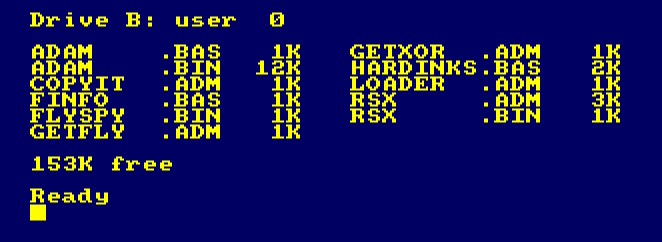
The Disk
The disk with the ADAM Environment and source code used in this project is available to download here :-
The developer of ADAM (Pascal Séguy) aka DAMS in Europe has kindly provided permission for me to include his amazing tool with the Disk Image. Which means you have no excuses to not play around with the same version I had in the 80s. You can find Pascal’s work over on GitHub
https://github.com/pseguy/dams/tree/master
The disk contains the following Files :-
| File | Info |
|---|---|
| ADAM.BAS | ADAM Assembler IDE, with Permission from Pascal Séguy |
| FINFO.BAS | Run this once to load the RSX FileInfo Tool |FINFO,”Filename” |
| RSX.ADM | Source Code for the Fileinfo Command |
| RSX.BIN | Assembled Binary File loaded by FINFO.BAS |
| HARDINKS.BAS | A BASIC Program to convert Hardware Ink Colours to Software |
| GETFLY.ADM | Source Code to load the initial tape loader from Fly Spy |
| GETXOR.ADM | Source Code to load the initial tape loader and decode the loader from FlySpy |
| COPYIT.ADM | Source Code to transfer Fly Spy from Cassette to Disk |
| LOADER.ADM | Source Code for the Disk Loader for FlySpy |
| FLYSPY.BIN | Final Loader to load an run your transferred Fly Spy game code. |
Final Notes and Full Annotated Fly Spy Loader Code
In a future blog post I will cover off the actual turbo loader itself and how that worked. From detecting the file header to loading the data. To whet your appetite I’ve included the full annotated Source Code from my notes. How cool is that!
Thanks for tuning in!
Jason, aka The Argonaut, aka The Happy Hacker, aka The Happy Cracker and many more pseudonyms!
#  40   DI                  F3				; Disable Interrupts
#  41   LD   BC,#7F8D       018D7F
#  44   OUT  (C),C          ED49			; Switch off Upper/Lower ROM and Set MODE 1
#  46   LD   HL,#310        211003			; HL = #310
;
; Basically a routine to wipe all memory from #310 through to #FFFF
; and loopback round to #0000 - #003F
;
Loop1
#  49   LD   (HL),#00       3600			; POKE (HL),0
#  4B   INC  HL             23				; HL = HL + 1
#  4C   LD   A,H            7C				; A = H
#  4D   OR   A              B7				; Is H = 0?
#  4E   JR   NZ,#49         20F9			; If not back to Loop1
#  50   LD   A,L            7D				; Check L
#  51   CP   #3F            FE3F			; L = #3F? Basically checking if HL = #003F
#  53   JR   NZ,#49         20F4			; Back to Loop 1 if not.
#  55   IM   1              ED56			; Set Interrupt Mode 1
#  57   JR   #70            1817			; Continue execution

;
; CRTC Initialisation Data Table
;
#  59   NOP                 00
#  5A   NOP                 00
#  5B   CCF                 3F
#  5C   JR   Z,#8C          282E
#  5E   ADC  A,(HL)         8E
#  5F   LD   H,#00          2600
#  61   ADD  HL,DE          19
#  62   LD   E,#00          1E00
#  64   RLCA                07
#  65   NOP                 00
#  66   NOP                 00
#  67   JR   NC,#69         3000
#  69   NOP                 00
#  6A   NOP                 00
;
; Hardware Colour Table
;
#  6B   INC  D              14				; 0  - Black Border
#  6C   INC  D              14				; 0  - Ink 0 Black
#  6D   RLA                 17				; 11 - Ink 1 Sky Blue
#  6E   INC  B              04				; 1  - Ink 2 Blue
#  6F   DEC  D              15				; 2  - Ink 3 Bright Blue
;
; Initialise the CRTC Registers
;
#  70   LD   BC,#BC00       0100BC			; CRTC Register
#  73   LD   HL,#5B         215B00			; Point HL to a DATA Block
#  76   OUT  (C),C          ED49			; Write to CRTC Command Register
#  78   INC  B              04				; Set to Data Register #BDxx
#  79   LD   A,(HL)         7E				; Get data from Table
#  7A   OUT  (C),A          ED79			; Write to the CRTC Data Register
#  7C   DEC  B              05				; Set to Command Register #BCxx
#  7D   INC  C              0C				; C = C + 1
#  7E   LD   A,C            79				; A = C
#  7F   INC  HL             23				; HL = HL + 1 (Point to next data in table)
#  80   CP   #10            FE10			; Have we written 16 registers?
#  82   JR   NZ,#76         20F2			; If not loop back
;
;
;
#  84   LD   HL,#6B         216B00			; Memory Address for Hardware Colour Palette
#  87   CALL #8C            CD8C00			; Initialise the colour Palette
#  8A   JR   #A6            181A			; Continue from Address #A6


;
; Hardware Palette Initialisation
;
#  8C   LD   BC,#7F10       01107F			; Video Gate Array, #7F10 = Border Colour
#  8F   OUT  (C),C          ED49			; Request Write to Border Colour Palette
#  91   LD   A,(HL)         7E				; Get Data from Table = #14
#  92   OUT  (C),A          ED79			; Write new Hardware Colour to Register
;
; This was bugged, the value used was #14 in the table, this could not be written
; Bit 6 must be set to write the value.  It was probably ignored since the border
; will flash when loading the code anyway.
;
#  94   LD   C,#00          0E00			; Set C = 0, we're going to write from #7F00 to #7F03
#  96   INC  HL             23				; HL = HL + 1, next colour entry in table
#  97   OUT  (C),C          ED49			; Prime Palette Register
#  99   INC  C              0C				; C = C + 1, Point to Next Colour Register
#  9A   LD   A,(HL)         7E				; Get Colour From Table
#  9B   OR   #40            F640			; Set Bit 6 to Write the Value
#  9D   OUT  (C),A          ED79			; Set the new Colour Value.
#  9F   INC  HL             23				; HL = HL + 1, []
#  A0   LD   A,C            79				; Check if we've written four colours
#  A1   CP   #04            FE04            ; Compare to maximum colours for MODE 1
#  A3   JR   NZ,#97         20F2 			; Loop back if not
#  A5   RET                 C90				; Hardware Colour Palette set.

;
; Final Pre-Flight Checks and Game Loader Code.
;
#  A6   CALL #F0            CDF000			; Check if any ROMS are loaded
#  A9   LD   SP,#30F        310F03			; Set the Stack to below code load
#  AC   LD   IX,#310        DD211003		; Load Address Start
#  B0   LD   DE,#3FFF       11FF3F			; Number of Bytes to Load
#  B3   CALL #11F           CD1F01			; Load #3FFF Bytes to #310 Turbo Styleee
#  B6   LD   HL,#310        211003
#  B9   LD   DE,#C000       1100C0
#  BC   LD   BC,#3FFC       01FC3F			; Display the Loading Screen
#  BF   LDIR                EDB0			; Copy the data in memory #310 to Screen
#  C1   LD   IX,#310        DD211003		; Set Load Address
#  C5   LD   DE,#5000       110050			; Load #5000 Bytes to #310
#  C8   CALL #11F           CD1F01			; Load the Code from Cassette
#  CB   LD   DE,#6950       115069			; IX = #5310, Request another #6950 Bytes
#  CE   CALL #11F           CD1F01			; Load More Code
#  D1   LD   SP,#FFFF       31FFFF			; IX = #BC60, Reset Stack to Top of Screen memory
#  D4   LD   HL,#EB         21EB00			; Send some more code to Screen
#  D7   LD   DE,#C7D1       11D1C7
#  DA   PUSH DE             D5				; Execution will continue from #C7D1
#  DB   LD   BC,#05         010500			; Copying Five Bytes from #EB
#  DE   LDIR                EDB0			; Copy Data to Screen
#  E0   LD   HL,#310        211003			; Initialise the Registers
#  E3   LD   DE,#100        110001			; To Shift the entire code
#  E6   LD   BC,#B950       0150B9			; to the final location for #B950 bytes
#  E9   DI                  F3				; Make Sure Interrupts are disabled.
#  EA   RET                 C9				; Return - Will Jump to #C7D1 which will execute
											; The two instructions below
;
; Code to copy to the screen.
;
#  EB   LDIR                EDB0
#  ED   JP   #7756          C35677
;
; Check if any Non-Standard ROMS are installed.
;
#  F0   LD   BC,#7F00       01007F			; Video Gate Array - Does more than video
#  F3   LD   C,#85          0E85			; Switch Upper ROM on, retaining MODE 1
#  F5   OUT  (C),C          ED49			; Enable Upper ROM
#  F7   LD   B,#DF          06DF			; #DFxx is Expansion Rom Select
#  F9   LD   C,#00          0E00			; C = ROM 0
#  FB   OUT  (C),C          ED49			; Switch ROM 0 in
#  FD   LD   A,(#C000)      3A00C0			; Get Byte from ROM
# 100   BIT  7,A            CB7F			; Bit 7 Set?  CPC BASIC ROM
# 102   JR   NZ,#113        200F			; BASIC ROM Found goto #113
# 104   CP   #02            FE02			; Check ROM Type
# 106   JR   Z,#11C         2814			; If Extension ROM, Kill the program.
# 108   CP   #01            FE01			; Check if Background ROM
# 10A   JR   NZ,#11C        2010			; If not Background ROM, Kill the Program.
# 10C   LD   A,(#C073)      3A73C0			; Looking for AMSDOS, Specific Byte
# 10F   CP   #50            FE50			; If Not AMSDOS, Kill the program
# 111   JR   NZ,#11C        2009			;
# 113   INC  C              0C				; C = C + 1, look for next External ROM
# 114   JR   NZ,#FB         20E5			; Loop for 255 possible ROM Addresses.
# 116   LD   BC,#7F8D       018D7F			; Switch Upper ROM off
# 119   OUT  (C),C          ED49
# 11B   RET                 C9				; Check Complete, no extra ROMS detected.
# 11C   JP   #133           C33301			; Kill Code routine.

;
; Cassette Motor Control Routine
;
# 11F   LD   B,#F6          06F6			; µPD8255 Port C Data Port
# 121   LD   A,#10          3E10			; Enable the Cassette Motor Relay
# 123   OUT  (C),A          ED79			; Switch the Relay On
# 125   LD   A,#FF          3EFF			; Initial Value
# 127   SCF                 37				; Set Carry Flag
# 128   CALL #143           CD4301			; Load Data from Cassette
# 12B   LD   B,#F6          06F6			; Disable the Cassette Motor
# 12D   XOR  A              AF				;
# 12E   OUT  (C),A          ED79			; Switch the Motor Relay Off
# 130   LD   A,D            7A				; Check add expected data loaded
# 131   OR   E              B3				; Does DE = #0000?
# 132   RET  Z              C8				; If so, return otherwise... Kill Code Time.
;
; Kill Code - Erase Memory, though the LDIR will stop at address #13F
; leaving three bytes, to loop infinitely.
;
# 133   LD   HL,#143        214301			; Point HL to #143
# 136   LD   (HL),#00       3600			; POKE (#143),#00
# 138   LD   DE,#144        114401			; Set DE to #144
# 13B   LD   BC,#FFFF       01FFFF			; BC Counter to maximum 65535
# 13E   DI                  F3				; Disable Interrupts
# 13F   LDIR                EDB0			; Copy 00 byte to all addresses
# 141   JR   #141           18FE			; Lock the Processor, infinite loop
;
; The Actual Turbo Loader Routine
;
# 143   EX   AF,AF          08				; Switch to AF' Compliment (Alternate AF Register)
# 144   PUSH AF             F5
# 145   POP  HL             E1				; HL = AF
# 146   LD   (#205),HL      220502			; Preserve this at address #205
# 149   EX   AF,AF          08				; Switch back to AF
# 14A   LD   HL,#208        210802
# 14D   PUSH HL             E5				; Final Execution return address is #208
# 14E   INC  D              14				; Increment Data Length High Byte - Will Set A Flag to NZ
# 14F   EX   AF,AF          08				; Swap AF'
# 150   DEC  D              15				; Restore D to original.  Previous is to set a flag which
											; Will be checked after the header has been loaded
											; This will contain a single BYTE that will prime the inital
											; XOR Value for the data from cassette
											; HEADER BLOCK, Initial XOR Byte, DATA for DE Bytes.
# 151   LD   B,#F5          06F5
# 153   IN   A,(C)          ED78			; Read in from #F500 Channel B (Input)
# 155   RRA                 1F				; Bit 7 = Data from Cassette
# 156   RRA                 1F				; A = A / 4 or A >> 2, Bit 7 now in Bit 5
# 157   AND  #20            E620			; Mask with Bit 6 (Datacorder Cassette Read Data )
# 159   OR   #02            F602			; Set Bit 1
# 15B   LD   C,A            4F				; C will be set with Data on Cassette and Bit 1 Set
# 15C   CP   A              BF				; Reset Carry Flag and Compare if Equal to self...
;
; Search for Start of Data, looking for signal changes on cassette port.
; Also handles and detects none headers this was designed to search for.
; by using timing cycles.  B will contain a value of the number of cycles the signal was held
; in the same state (High or Low), and be incremented each loop.  When the state changes
; the detection routine quits with B set to a Value... that value is compared
; to see if a threshold has been reached.
;
# 15D   RET  NZ             C0				; Quit if Datacorder Not Ready or Error Condition
# 15E   CALL #1D7           CDD701			; Wait for signal to be received
# 161   JR   NC,#15D        30FA			; No change in signal found? Loop and Search
# 163   LD   HL,#415        211504			; Delay/Loop Counter
# 166   DJNZ #166           10FE			; Waste Cycles
# 168   DEC  HL             2B				; HL = HL -  1
# 169   LD   A,H            7C
# 16A   OR   L              B5				; HL = 0 ?
# 16B   JR   NZ,#166        20F9			; Waste more cycles and loop HL Times.
;
; HL = #0000
; Search for the start of the Data Header
; Using a combination of timed loops.
;
# 16D   CALL #1D3           CDD301			; Wait 2 * Time for Cassette signal change
# 170   JR   NC,#15D        30EB			; Repeat if not found in time.
											; Carry is Set if Successful
											; NZ is Set if Error Condition
;
; Wait for next state change
;
# 172   LD   B,#9C          069C			; Set B = Specific Time Period To Wait
# 174   CALL #1D3           CDD301			; Wait two times
# 177   JR   NC,#15D        30E4			; Loop again if no change detected.
;
; First Timed Header Cycle, if Counter B < #C6, Signal not long enough, start again...
;
# 179   LD   A,#C6          3EC6
# 17B   CP   B              B8				; Determining if the length of signal was #C6 or
# 17C   JR   NC,#15E        30E0			; Change State not found, loop and search again.
;
; First Part Header Test Passed, lets keep searching...
;
# 17E   INC  H              24				; Count the number of times around the loop.
# 17F   JR   NZ,#172        20F1			; Header not yet found, loop again and keep searching
;
; Prime B with Start Seed Value for loop counter
;
# 181   LD   B,#C9          06C9			; Start Seed Timer Counter
# 183   CALL #1D7           CDD701			; Wait for next state change
# 186   JR   NC,#15D        30D5			; If no data or error found loop again.
;
; Check the length of the signal change/time to change state.
;
# 188   LD   A,B            78				; B = Count of Signal Length
# 189   CP   #D4            FED4			; Compare with #D4
# 18B   JR   NC,#181        30F4			; If less than, loop some more.
;
; Need a longer Signal State Change
;
# 18D   CALL #1D7           CDD701			; Look for final state change
# 190   RET  NC             D0				; Quit if Error/No Valid Data.

# 191   LD   A,C            79				; A = C = Next state to check (Expected to be #02)
# 192   XOR  #03            EE03			; Invert Bits 0 and 1
# 194   LD   C,A            4F				; Store the Flipped the Bits Over
# 195   LD   H,#00          2600			; Set H = #00
# 197   LD   B,#B0          06B0			; Set B = #B0 next Timer counter...
# 199   JR   #1B8           181D			; Continue at #1B8, Header Search Complete
											; Now to Load the data
;
; Check if First Byte Loaded is Valid, Will be #FF in testing.
; C will be set to either #01 or #FE
;

# 19B   EX   AF,AF          08				; Restore Preserved AF'
											; This is always set at the start of the header check.
											; It's a flag to say the first byte of data data after
											; the header.
# 19C   JR   NZ,#1A8        200A			; First Time Byte, Run This Check
# 19E   PUSH AF             F5				; Preserve AF - Flags
# 19F   LD   A,L            7D				; L = 8 Bits of Data Loaded
# 1A0   XOR  D              AA				; XOR with current MSB of Length
# 1A1   LD   L,A            6F				; L = A
# 1A2   POP  AF             F1				; Restore AF
# 1A3   LD   (IX+#00),L     DD7500			; Write Data to Memory location in IX
# 1A6   JR   #1B2           180A			; Forward to increment points etc.
;
; The first byte after loading the header is the initial XOR Byte...
; Fly Spy L = #FF, C = #01
; If not #FF then something went wrong possibly...
;
# 1A8   RL   C              CB11			; C = C * 2 + Carry Bit
# 1AA   XOR  L              AD				; Xor with L (Initial Byte Loaded)
# 1AB   RET  NZ             C0				; If the byte is non-zero probably error.
# 1AC   LD   A,C            79				; Get C
# 1AD   RRA                 1F				; Shift Right >> 1 or /2
# 1AE   LD   C,A            4F				; C = Initial Value Again
# 1AF   INC  DE             13				; Increment DE to Counter Decrement
# 1B0   JR   #1B4           1802			; Could have skipped above and JR #1B5 Instead.
;
; Increment memory pointers, decrease Data to Load Counter
;
# 1B2   INC  IX             DD23			; IX = IX + 1, Next Memory Address to Store Data
# 1B4   DEC  DE             1B				; DE = DE - 1, Count Down Number of Bytes
# 1B5   EX   AF,AF          08
# 1B6   LD   B,#B2          06B2			; Initialise B = Count Value.
;
; Load a byte of data from the Cassette, the trick is familiar.  Carry is Clear
; L is initialised with #01, as each bit is rotated into L << 1, the Eighth rotation
; will force Carry to be set, signalling 8 Bits of Data have been loaded into L
; Simple trick used in many a tape loader, see more on my Novaload Explained example.
;
; B is set to a counter value.  #B0, the read bit loop increments B until a
; change in signal is detected.  The value is compared to #C0,
; less than or Equal = 1 Bit, greater than = 0 Bit.  Carry is set accordingly
; The result of that compare is rotated into L, i.e. the Carry Flag moves into
; Bit 0 of L.
;
# 1B8   LD   L,#01          2E01			; Initialise L to 1 - This will be
											; Ensure the Carry Bit Set on 8th RL L instruction.
# 1BA   CALL #1D3           CDD301			; Wait for Bit Signal Change on Cassette Port
# 1BD   RET  NC             D0				; Quit if Error
# 1BE   LD   A,#C0          3EC0			; Threshold Counter for 1 / 0 Bit
# 1C0   CP   B              B8				; Carry is Set if B > #C0 , 1 Bit else 0 Bit of data
# 1C1   RL   L              CB15			; Carry Bit is Rotated Left into L %00000001, becomes
											; L %0000001C Carry Bit
											; Will continue until the Carry Bit is Set when...
											; L = %1CCCCCCC << C final carry bit.
# 1C3   LD   B,#B0          06B0			; Set B = #B0 - Timer Counter Start
# 1C5   JP   NC,#1BA        D2BA01			; Loop for 8 Bits (Waiting on Carry Set on L)
# 1C8   LD   A,H            7C				; Value in H is used to decode the byte on cassette
# 1C9   XOR  L              AD				; XOR With Byte Loaded from Cassette
# 1CA   LD   H,A            67				; Set H = A - Seed H with the next value.
# 1CB   LD   A,D            7A				;
# 1CC   OR   E              B3				; Check if DE Reached Zero
# 1CD   JR   NZ,#19B        20CC			; If more Data to Load loop back to #19B
# 1CF   LD   A,H            7C				;
# 1D0   CP   #01            FE01			; Not used, could have been some sort of CRC Check?
# 1D2   RET                 C9
;
; Wait double the time for change of signal.
;
# 1D3   CALL #1D7           CDD701				; Call code to waster cycles and time changes
# 1D6   RET  NC             D0					; to 0/1 from Tape.  Quit if error
;
; Wait a small period of time, detect a change in cassette signal
; 0 -> 1 or 1 -> 0 depending on previous state stored in C
;
# 1D7   LD   A,#10          3E10				; Set Loop Counter
# 1D9   DEC  A              3D					; Decrement Counter
# 1DA   JR   NZ,#1D9        20FD				; Loop until Zero 65 µS
# 1DC   AND  A              A7					; Reset Carry Flag
# 1DD   INC  B              04					; Going to loop 10 times until B = #00
# 1DE   RET  Z              C8					; Check if B = 0 - No signal received
# 1DF   LD   A,#F5          3EF5
# 1E1   IN   A,(#FF)        DBFF				; A = Read Port #F500
# 1E3   RRA                 1F
# 1E4   RRA                 1F					; A >> 2 or A = A / 4, Bit shift Right by two
# 1E5   XOR  C              A9					; C = Previous State, Looking for a Bit Change
# 1E6   AND  #20            E620				; Data Signal Received?
# 1E8   JR   Z,#1DD         28F3				; Loop until a change in signal.
# 1EA   LD   A,C            79					; A = Previous Bit State
# 1EB   CPL                 2F					; Invert A (Complement)
# 1EC   LD   C,A            4F					; Set C to next BIT state to search
# 1ED   PUSH BC             C5					; Preserve BC
# 1EE   LD   A,#10          3E10
# 1F0   LD   B,#7F          067F				; We're going to change the border colour
# 1F2   OUT  (C),A          ED79				; Set border colour to value in A
# 1F4   LD   A,(#207)       3A0702
# 1F7   INC  A              3C					; A = A + 1
# 1F8   AND  #1F            E61F				; A = MOD #1F
# 1FA   LD   (#207),A       320702				; Store next colour
# 1FD   ADD  A,#40          C640				; Set Bit 6 to write the colour to Video Gate Array
# 1FF   OUT  (C),A          ED79				; Write the new BORDER Colour
# 201   POP  BC             C1					; Restore BC
# 202   LD   A,C            79					; Set A = C
# 203   SCF                 37					; Set Carry Flag = Success!
# 204   RET                 C9					; Return
;
; Next two bytes preserve the Alternate AF Register
;
# 205   NOP                 00
# 206   NOP                 00
;
; Counter for border colour to use.
;
# 207   DEFB #02 				;

;
;	Restore the Alternate AF' Register preserved in #205
;

# 208   EX   AF,AF          08				; Swap back to alternate register
# 209   LD   HL,(#205)      2A0502			; Get the preserved value in #205
# 20C   PUSH HL             E5
# 20D   POP  AF             F1				; AF = HL
# 20E   EX   AF,AF          08				; Switch back AF Alternate register
# 20F   RET                 C9				; End of Routine

