
Amstrad CPC Magnum Light Gun

The following analysis has been taken using physical hardware and disassembling the code on the disk provided with the Light Gun.
Hardware used:
- Amstrad CPC6128
- Amstrad Magnum Light Gun
- Amstrad CTM644 Colour Monitor
Software Used:
- A.D.A.M. (aka DAMS in France) – Assembler, Disassembler and Monitor
- Mastertronic Original Light Gun Entertainment Pack
A.D.A.M. was my tool of choice back in the 80’s due to the way the entire package allowed me to single step and debug Mnemonics/OpCodes, plus it can be loaded into an extended bank of memory, which meant in the event of a crash, I could pick up where I left off without having to reload the system.
A disk of six games were included with the Magnum light gun. Side A included modified Mastertronic titles such as ITV’s Bullseye, the flip side contained a modified version of Operation Wolf, and this was probably the highlight of the package since this provided the arcade experience many home computer users craved.
The hardware is physically tied directly to Port #FBFE, no direct mapping is provided to Keyboard or Joystick input. The lightgun acts as and uses the lightpen control, for accuracy the sensor needs to be operated approx. 1.2m away from the CRT Monitor.
The electronics for the light gun is rather simple, containing a photosensitive diode and trigger circuitry. The Photodiode is sensitive enough to detect the CRT Write signal to the screen, most games were required to flash the screen white to ensure this signal was picked up. Some games could be coded to display white blocks to target at without the distracting flash. In practice, bright colours, like Yellow or White worked well in testing.
To use the device accurately, the hardware must wait for V.SYNC signal from the monitor (Also known as Frame Fly Back or CALL #BD19), where the electron beam has finished writing screen information and moves quickly from the bottom right corner to the top left corner before waiting and writing screen data once again. For UK Monitors this occurs every 1/50th second. Technology like screen displays rely heavily on the persistence of vision since most humans only need 24 frames per second to look like a movie and not a highspeed slide show.
To explain this better, take a look at this short video from The Slow Mo Guys : https://www.youtube.com/watch?v=3BJU2drrtCM
When pointed at the screen, the photo diode is waiting to detect a trigger from a light source (The electron beam hitting phosphor on the screen) which occurs at ~1.5μS When detected it sends a rising edge signal to the Light Pen connector on the expansion port (47).
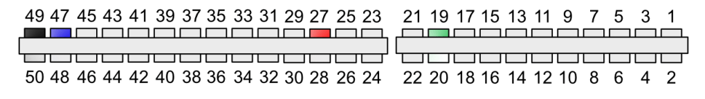
- 19 = Data Line 7
- 27 = VCC (+5v)
- 47 = Light Pen Signal
- 49 = GND (Ground)
Detecting the Trigger Button
Detecting when the Light Gun Trigger is pulled appears straight forward, send two signals to the Light Gun Device to reset and set Bit 7 by writing to port #FBFE, this is because the light gun is connected to the D7 Address line on the expansion port, D0-D6 are unused. This “Primes The Trigger” to only read when the trigger is pressed during that cycle (the next write of the screen) will occur within the screen write process after frame flyback.
          LD   bc,#fbfe
          LD   a,#7f           ; Bit 7 Reset, 0-6 Set (Could use 0)
          OUT  (c),a           ; Write #7F to Port #FBFE – Light Phaser – Falling Edge
          INC  a               ; Bit 7 Set, 0-6 Reset
          OUT  (c),a           ; Write #80 to Port #FBFE – Light Phaser - Leading Edge
The code simply writes 0x7F (01111111) followed by 0X80 (10000000) to port #FBFE to force a trailing edge followed by leading edge on D7 which informs the gun to only send a signal on the Light Pen Port when the trigger is pressed. This ensures that data from the CRTC Registers are Written only when the trigger is pressed during that cycle.
It basically completes a circuit to check for and detect a light source, If the LightPen Signal goes high, the CRTC registers “Remember” the location when the photodiode registered a hit. CRTC Register 17 (Low Address) and CRTC Register 16 (High Address) are halted until the V.SYNC Signal is sent. After each V.SYNC the registers continue updating and therefore the data is unreliable. If you see unreliable data, check that the room you’re in, isn’t too bright and you’re holding the gun away from the screen.
The accuracy of the LightPen CRTC Registers is noted to two screen bytes wide and 9 Scan Lines Down, though we tend to use 8 Scan lines. This provides an accuracy of a MODE 1 character block of 40 x 25. You could add some variation to the accuracy assuming that most users don’t have the motor skills of a world class surgeon and add a random element of four scan lines above and below to give the impression of a larger range of accuracy on screen.
Code to Detect the Light Gun Trigger
The following code snippet is taken from my GitHub: https://github.com/muckypaws/AmstradCPC/blob/master/Assembly/LightGun/LightGunFire.asm
         DI                  ; Disable Interrupts
Start:
         LD   bc,#bc00
         LD   a,#11
         OUT  (c),a          ; Request CRT Register 17 (Light-pen Address Low)


         LD   bc,#bf00
         IN   e,(c)          ; Read CRT Data Register 17 #BFxx

                             ; Raise a Falling Edge on the Light Gun Input
         LD   bc,#fbfe
         LD   a,#7f          ; Bit 7 Reset, 0-6 Set (Could use 0)
         OUT  (c),a          ; Write #7F to Port #FBFE – Light Phaser – Falling Edge

         INC  a              ; Bit 7 Set, 0-6 Reset
         OUT  (c),a          ; Write #80 to Port #FBFE – Light Phaser - Leading Edge


         LD   bc,#bf00
         IN   a,(c)          ; Read Value from CRT Data Register 17 #BFxx

         CP   e              ; If Previous Read Value = Current Read Value Then Fire
                             ; Pressed and LightPen Position detected

         LD   A,0             ; Don’t want to reset the F Register…
         JR   nz,RegisterFire ; If Fire Not Pressed Store Null Value
         DEC  A               ; Set Flag to Non-Zero if Fire Pressed

RegisterFire:
         LD   (FireData),a    ; Store the Flag
         EI                   ; Enable Interrupts
         RET

FireData: DEFB 0              ; Trigger Pressed Flag
Using this simple test harness, The Fire Button is detected as active when the two IN (Reads) on Port #BFxx contain the same value. Basically, the CRTC Light Pen Registers were “Remembered” for the Frame which was being written at (1/50th Second).
In testing, the values returned appeared to be random. However, when the light gun is placed on the screen, these values change randomly whilst the fire button is pressed. When the light gun is pulled away from the screen, a Random value is generated but consistent.
In simple Terms.
- Disable Interrupts
- Request CRT Register 17 (light Pen address Low)
- Read the CRT DATA Register 17
- Send a trailing edge, following by leading edge signal to the lightgun to ensure lightgun is readied to read correct signal.
- Write to the Light Gun setting all low bits high (0-6) and then Set Bit 7 High
- Forces a Leading Edge Signal to read CRT LightPen registers
- Read the CRT DATA Register 17 again
- Compare the Register 17 with old value read from step 3
- If the Values aren’t equal, Fire Button Not Pressed
- If Values are equal, Fire Button Pressed.
- Set Fire Flag, 0=Not Fired, 255=Fired.
Screen Detection Code
Taken from the Magnum Light Phaser GUN.BIN code on Disk Side A, Also available on my GitHub Repository: https://github.com/muckypaws/AmstradCPC/blob/master/Assembly/LightGun/MagnumLightGunDetectionRoutine.asm
For reasons unknown, WordPress seems to take the formatting to new lows for code… I swear it didn’t look like this…
                ORG     #A000
;
                JP      GetScreenCoords        ; Get X,Y Co-Ordinates of LightGun
                JP      CheckTrigger           ; Check If Trigger Pressed
XCoord:        DEFB 0                        ; Store X Address (Each Represents two bytes)
YCoord:         DEFB 0                       ; Store Y Address (Each Represents 8 Scan Lines)
Temp1:         DEFW 0                          ; Work Area 1

GunFired:       DEFB 0                       ; Flag for Trigger Pressed
GetScreenCoords:
                LD      HL,&FFFF
                LD      (XCoord),HL            ; Set X & Y To Invalid 255,255
                CALL    &BC0B                 ; Get The screen offset (Hardware Scroll)
                                           ; HL = Current Offset, A = MSB of Base Address
                SRL     H
                RR      L                       ; HL = HL / 2
                LD      (ScreenOffset),HL      ; Store Half Value of Offset
                SRL     A
                SRL     A                       ; A = A / 4
                OR      H                     ; Or H
                LD      (BaseScreenAddress),A   ; Store Modified Screen Offset
                CALL    &BD19                  ; Call FrameFly Back (Wait for CRT to finish)

                DI                             ; Disable Interrupts
                LD      B,&BC
                LD      A,&0C
                OUT     (C),A                 ; Select CRT Register 12 (Display Address High)
                LD      A, (BaseScreenAddress)  ; Get Base Screen Address
                OR      &08                     ; Set Bit 4
                LD      B,&BD                  ; Set Screen to Offset
                OUT     (C),A                   ; Writing to #BDxx
                LD      C,&FF
                LD      DE,&FEE4
RequestReg16:
                LD      B,&BC
                LD      A,&10                   ; Request CRT Register 16 (Light Pen Address High)
                OUT     (C),A
                LD      B,&BF
ReadRegister16:
                IN      A,(C)                   ; Read Register #BFxx
                LD      H,A                     ; Preserve CRT High Register Value
                AND     &08                     ; Is Bit 4 Set?
                JR      NZ,ReadLightPenLow     ; If Set, Read Register 17 (Light Pen Low Address)
                DEC     IX                    ; Waste Cycles
                INC     E
                JR      NZ,ReadRegister16       ; Perform 26 Cycles... then 256
                INC     D
                LD      A,&05                   ; Perform 7 More Cycles
                CP      D
                JR      NZ,ReadRegister16       ; Continue to Read Register 16
                INC     C
                JR      NZ, CalculatePosition   ; Calculate Position of LightGun
                EI                              ; Enable Interrupts
                RET                             ; Quit to Caller
ReadLightPenLow:
                LD      B,&BC
                LD      A,&11
                OUT     (C),A                   ; Request register #BCxx,17
                LD      B,&BF
                IN      L,(C)                   ; Read Register
                LD      IY,(RegisteredAddress)
                LD      (RegisteredAddress),HL  ; H = High Address, L = Low Addres
                LD      (Temp1),DE              ; Store DE in Temp Work Area (Not Used)
                INC     C
                LD      A,&0A
                CP      C                       ; Waste More Cycles until C = 10 (255 Iterations)
                JR      NZ,RequestReg16
CalculatePosition:
                DI
                LD      B,&BC
                LD      A,&0C
                OUT     (C),A                  ; Request CRT Register 12 (Screen Base Address)
                LD      A,(BaseScreenAddress)
                AND     &F7
                LD      B,&BD
                OUT     (C),A                 ; Write Screen Offset Address Back
                CALL    CheckTrigger           ; Has the Trigger Been Pressed?
                LD      A,(GunFired)
                OR      A                     ; Check Trigger Flag
                RET     Z                     ; Quit if Not Pressed

                LD      HL,(RegisteredAddress) ; Get Registered Address
                CALL    Adjust                  ; Divide by 40 and Adjust for Half Screen Offset
                PUSH    AF                      ; A = Y COORD
                PUSH    IY
                POP     HL                      ; HL = IY
                CALL    Adjust                  ; Divide by 40 and adjust for screen offset
                LD      (XCoord),A              ; Set X-Coord This time
                POP     AF                      ; Restore A
                CP      L
                RET     NC                      ; if A >= L then finish

                LD      (XCoord),A              ; Otherwise Store Lower Value
                RET

                ; Inefficient Routine to work out Block X, Y Position of the Lightgun
Adjust:
                LD      A,H                    ; Get High Address
                AND     &03                     ; Mask first Two Bits
                LD      H,A                    ; For H to mask two low bits
                LD      DE,&0003
                SBC     HL,DE                  ; Subtract 3 from HL
                XOR     A                     ; Reset A
                LD      DE,(ScreenOffset)      ; Load Screen Offset
                SBC     HL,DE
                JR      NC,Adjust2
                LD      DE,&0400
                ADD     HL,DE                 ; Add #400
Adjust2:
                LD      DE,&0028               ; DE = 40 (Half Line Width)
                XOR     A
Adjust3:
                SBC     HL,DE                  ; Subtract 40
                JR      C,Adjust4
                INC     A
                JR      Adjust3               ; Inefficient / 40 to find X-Coord
Adjust4:
                ADD     HL,DE                 ; Add 40 back so not in fraction
                LD      (YCoord),A              ; Store in Y-Coord
                LD      A,L                     ; A = L  (Remainder)
                RET

; Check if Light Gun Trigger has been pressed

CheckTrigger:   CALL    &BD19                  ; Wait for Frame Fly Back
                DI                              ; Disable Interrupts
                LD      B,&BC
                LD      A,&11
                OUT     (C),A                   ; Write to CRT Register 17
                LD      B,&BF
                IN      A,(C)
                LD      E,A                   ; Read Register Status
                LD      BC,&FBFE
                LD      A,&7F
                OUT     (C),A                 ; Send Low Signal to Light Gun
                LD      A,&80
                OUT     (C),A                   ; Send Leading Edge Signal to Light Gun
                LD      B,&BF
                IN      A,(C)                   ; Read CRT Register 17 again
                EI                              ; Re-Enable Interrupts
                CP      E                       ; Was the OLD Register and New Register Equal?
                LD      A,&FF                   ; Set Fire Flag Status in Readiness
                JR      Z,StoreFire             ; If Equal Jump to Write Flag
                XOR     A                       ; Zero Out Flag
StoreFire:
                LD      (GunFired),A            ; Write Flag
                RET                             ; Return to Caller

BaseScreenAddress:     defb 0                ; Base Screen Address
ScreenOffset:          defw 0                ; Define Screen Offset


RegisteredAddress: DEFW 0
Light Gun Coordinate Detection
Seems a bit of an odd one here.
In general, the routine will read the CRT Registers High and Low address for a LightPen (CRT Registers 16/17), with some built in delay code to ensure false readings are mitigated, i.e time has sufficiently passed for the CRTC to write to the screen for that frame before flying back.
The code will make the relevant calculations to adjust the address if the screen has hardware scrolled, meaning the screen base address is no longer 0xC000 to calculate the actual location the player fired at.
- Wait for CRT Frame Fly Back. (V.SYNC Signal)
- Read CRT Register 16 (light Gun High Register) and check if BIT 4 is set
- If BIT 4 is NOT set then loop around and waste wasting cycles (delay)
- If still not set after X iterations, then quit (This is code protection should the lightgun not be present to avoid an infinite loop)
- Read CRT Register 17 and continue reading for 255 cycles (weird)…
- H = High Register, L = Low Register
- Check if Gun Fired – forces another V.SYNC Wait to ensure button not pressed at the end of a screen write.
- If Fired, adjust HL to X, Y Coords addressing taking Hardware Scrolling into account.
- To find real X,Y
- Subtract 3 from the Lightpen CRTC Registers
- H = High Byte, L = Low Byte
- Mask with 0x3FF
- X = INT HL Divided by 40 (Half Screen Width).
- Y = INT HL Mod 40
- Store the X, Y results to be read by called.
Looking at the detection code it seems a little inefficient in places, especially the divide by 40 routine which can be optimised further than a simple subtraction loop.
Simulation
How can we effectively simulate the Magnum Light Gun?
Mappings Required: –
- PORT = #FBFE
- Expansion Port 19 – D7
- CRTC Registers 16/17
- Expansion Port 47 (Light Pen Input)
The Light Gun must be mapped to PORT #FBFE and listens for a signal on expansion bus Data Line 7. When D7 = 0 followed by 1 within 1 v.SYNC Signal when the trigger is pulled a leading edge (1) signal is sent to Expansion Port 47 to notify and update CRTC Registers 16/17 based on position of the screen draw at the point of detection.
Using a simple Basic Program, I use this to test and read the CRTC registers and when Fire is pressed to display an X on the screen of the position the lightgun was read. Very Simply and Effective to show you how it all fits together.
The Code was created using the full source above.
10 BORDER 26:INK 0,26:INK 1,0:PAPER 0:PEN 1
20 fire = 0
30 MEMORY &7FFF:IF PEEK(&A000)<>&C3 THEN LOAD"!code.bin"
40 MODE 1:GOSUB 80:size=40:ys0=1:ys1=6:g=0
50 CALL &A003:fire=PEEK(&A00A)
60 IF fire=0 THEN 50
70 CALL &A000:x=PEEK(&A006):y=PEEK(&A007)
80 CLS:LOCATE 1,1:PRINT "X,Y: ";x;", ";y
90 myval=PEEK(&A0EE)+(PEEK(&A0EF)*256):PRINT "Value = ";myval;" :";HEX$(myval)
100 PRINT "Div: ";INT(myval/40);" Mod: ";myval MOD 40
110 myval = myval AND &3FF
120 PRINT "Masked Div: ";INT(myval/40);" Mod: ";myval MOD 40
130 IF (x>0) AND (x<40) AND (y>0) AND (y<25) THEN LOCATE x,y:PRINT"X"
140 GOTO 50
Challenges
The main challenge is identifying the circuitry inside the Light Gun itself, since the gun is glued, the only way to get inside is breaking the plastic and rendering the device useless. given they are rare and currently valuable on eBay I’ve taken an educated guess as to what the circuitry might be inside the gun. If anyone has opened one of these up and can send me clear photographs of the parts and circuits I’ll be able to update it accordingly.
I’ve tested the circuit using breadboard and some off the shelf components and seems to work well.

I hope this helps provide some explanation on how the light gun works, I am open to peer review and questions/clarifications.


j’ai une photo du circuit du pistolet. comment te l’envoyer
LikeLiked by 1 person
That would be amazing! Use the contact sheet on about me and I can send you my email address etc.
LikeLike
Bonjour ,j aimerai avoir plus de detail concernant le circuit et les composant pour reproduire l’electronique interieur, aujourd hui on peu imprimé bcp de chose ,et il serai bien de pouvoir se “refabriquer” un pistolet fonctionnelle avec cette version 🙂
LikeLiked by 1 person