
NOVALOAD – Commodore Speed Load and Protection System Hacked.

I may have mentioned, back in the day I used to be a hacker software security engineer. Protection Systems back then were evolving at a fast and steady rate.
The home computers of old were notorious for slow loading, with some programs and games taking over 30 minutes or more, especially if you had that dreaded “Tape Loading Error”. Enterprising folks created a niche market creating “Speed Loaders” which loaded programs (and more importantly Games) in significantly less time.
I remember the first time I encountered one, I thought the tape was faulty with flashing coloured bars on the screen, and quicker than expected was greeted with the game running in it’s full Eight Bit Glory.
Though Speed loaders resulted in less magnetic tape required for mastering cassettes, they were designed to make it more challenging for the casual “Tape to Tape Playground Pirate”, with the inevitable “Protection System” as standard to make it harder for friends of “Captain Jack Sparrow” to copy 😂
In today’s blog, I’m going to focus on one of the earliest and rather ingenious Speedloader for the Commodore range of computers, which became prolific back in the day. Additionally all these years later, I haven’t found any information breaking this protection system down for the archivist or casual 6502 coder. At the time I first encountered this protection system I was about 13 years old, and had to work all this out from first principals, not bad for a kids eh? Today, I’m revisiting this for nostalgia reasons, and testing my memory of old.
You will need a working knowledge of 6502 Assembly Language to follow through. My C16 knowledge is a tad rusty to say the least. It was my second home computer (Yet I knew how to pick lemons having forgone the Spectrum for the VIC-20, and the C64 choosing a C16 instead). I made up for that by owning probably the best 8-Bit home computer “The Amstrad CPC6128”. #ShotsFired…. #ISaidWhatISaid…. #YepPlayground8BitRivaryIsStillAThing
The Boring Stuff
This article can not be published in physical or electronic media without express permission from the author (Me!). If you’re sharing the link to the article via social media, please use the direct link as every click helps.
What you’ll need.
To follow along, I recommend the following:-
- A working knowledge of 6502 Assembly Language Programming
- VICE – https://vice-emu.sourceforge.io
- YAPE – http://yape.homeserver.hu
- CBM Program Studio – https://www.ajordison.co.uk/download.html
- My GIT Repo: https://github.com/muckypaws/RetroCheats
- Memory Map – https://github.com/franckverrot/EmulationResources/blob/master/consoles/commodore/C16%20Memory%20Map.txt
A copy of this book or something similar

Novaload
The designers of this system were ahead of their time, or gifted developers, given that we didn’t have access to the wealth of information at our fingertips with today’s internet and archived manuals.
That’s a bold statement…
It certainly is, the designers understood the architecture of the machine very well, such that they created (What I believe to be) the first “Loader” that Auto-ran itself no matter how you tried to load the program.
Ordinarily, you type LOAD, the program loads allowing you to RUN or LIST to see the program. However, this little gem somehow managed to run the program without any intervention from the user. How?

The trick was elegant and stunningly simple. The loader code would overwrite the CPU Stack thus forcing execution of the code after the first block loaded. This was the corner stone of the “Protection System”, I’d only seen this technique repeated once on the Amstrad CPC Z80 processor with Richard Aplin’s “Fly Spy” Protection System.
What are you talking about Jason?

The Commodore Program Stack was fixed to Page 1 ($100 – $1FF) of memory, it was immovable. The Stack Pointer starts at $1FF and works its way downwards to $100 before cycling back to $1FF. Though if that happens you’ve got bigger problems with your program code.
Although the memory address is a fixed page range, the Stack Pointer consists of one byte, the “Page is Implied”. The Stack Pointer is set to the next free byte on the stack that data can be pushed to, popping data off the stack is always the address above.
The Current Stack Pointer is $F3, if we PUSHED the accumulator on the stack with PHA the data will be written to address $1F3 and the stack pointer decremented to $1F2.
When we POP the accumulator off the stack, the address $1F3 (The one above the SP is read) and the SP is incremented by one byte back to $1F3.
Essentially this system overwrote the area of Stack memory this taking control of the machine at the first RTS (Return instruction) since the stack contains a return address of it’s own intercept code.
The challenge the designers had was not only did they need to implement their loader code in just one block of data (256 Bytes) since that block will “Corrupt” the stack when written from cassette buffer to memory, they had to find a way to squeeze more bytes somewhere, simply because the whole loader code couldn’t reliably fit in 256 bytes, as the Stack would be unpredictable.
How did they get around this limitation? By hiding further code in the Cassette Data Header Structure!
Confused? Hopefully this will help illustrate the example.
Initial Loading
Let’s start at the very beginning… Thankfully using today’s tools like VICE or YAPE make our job much easier than it was in the 80’s
Throughout this example I’m going to use the Mastertronic Release of “Mr Puniverse”, the successor to “Big Mac”, for the following reasons. One I played this game to death back in the day, but also this features two turbo programs, the first in BASIC with a simple title page and the second the actual game.
Attach the “Mr Puniverse” Tape image to your emulator or real C16 if you’re going hardcore, type LOAD and as soon as the “FOUND MR PUNIVERSE” message appears, activate the emulator Monitor.

The tape buffer location is found in memory address $B6 and $B7, a dump of these addresses reveal the Tape Buffer is located at $0333, and according to my rather dog eared copy of “C16 Machine Language for the Absolute Beginner” The Tape buffer is found between $0333 – $03F2 (192 Bytes).
The first two bytes, points to the Memory Address to LOAD the data, in this case $0140

The next two bytes ($0335/$0336) is the last address to store the data.

The architecture of the Commodore Range of machines means we know that the STACK is tied to PAGE1: $0100 – $01FF

Interestingly PAGE1 has additional uses, the first 16 bytes are used for Floating Point Conversion buffer space, Colour Luminance Table and Kernel Save Information. Leaving only $0124 – $01FF for the actual system stack.

Depending on when you activated the monitor, you may see different data from the Stack Pointer, in this example, $1F3 is the pointer to the next free space on the system stack, when the current routine has completed execution the data in Addresses $1F4 and $1F5 contain the return address-1.
To try and illustrate.

Wait, what? Return address -1? Yep, bit of a strange concept if you’re familiar with Z80/8080 or 80×86 assembly development where the program counter of the next instruction is pushed to the system stack. In 6502 land when a Subroutine is called, the program counter contains the final byte of the calling address. i.e.
$1200   20 18 15   JSR $1518
$1203   EA         NOP
$1202 is where the Program Counter (PC) was prior to the Jump to Subroutine (last byte read) therefore this address is pushed to the stack, and not Program Counter + 1 ($1203). Madness I say, but that’s architecture for you. Thankfully the 6502 when popping data off the stack with an RTS instruction internally increments the Program Counter + 1 for the next instruction. In the example of the stack dump above the data $03 $EA will return execution to address $EA04.
Still with me? And that’s why systems developers earned the big bucks!
We know the System Stack is located in PAGE1, the program being loaded will overwrite the stack area too.

During the load process the Stack Pointer has been updated to point to $F4, meaning when the load is complete, the program counter of $0202 will be popped off the stack, which means a return address of $0203.
We can set a break point at $0203 to prove this, and resume execution.
BREAK $0203

The Loader
If you haven’t guessed already, this is how the designers ensured that there program code would be executed without user intervention, and also bypassed simple firmware “LOAD” routines like :-
*=$1200
     LDA     #$01
     LDX     #$01
     LDY     #$FF
     JSR     $FFBA
     LDA     #$00
     JSR     $FFBD
     LDX     #$40
     LDY     #$15
     JSR     $FFD5
     RTS
In this example the stack would always be “Corrupted” and the game would load as designed since program execution was forced to $0203 the moment an RTS instruction was encountered. Other protection systems we’ll cover in later articles utilised the Interrupt Vector to force their code to run, though this is a more thorough discussion in its own right.
Could the designers use a different address? Yes and No… This trick only works for the first block of data loaded into memory, the Stack pointer can not be guaranteed to point to an EVEN Address, as a hacker could push a value on the stack to try and defeat it. To guarantee auto run and minimal interference with the code, identical values need to be pushed. $0303 wouldn’t work as the kernel firmware loader only loads 256 byte blocks at a time, and 0101 would run the risk of corrupt data with firmware tables stored below $0122.
There’s still more to be done! Let’s take a look at the final code for loading the program.
(C:$0203) d
.C:0203  A9 01       LDA #$01
.C:0205  8D 3B 05    STA $053B      ; Set Active Colour To 1
.C:0208  20 84 FF    JSR $FF84      ; Initialise IO
.C:020b  A9 93       LDA #$93
.C:020d  20 D2 FF    JSR $FFD2      ; Print Screen Clear CHR$(147)
.C:0210  A9 8E       LDA #$8E       ; Switch to Upper Case CHR$(142)
.C:0212  4C 40 01    JMP $0140      ; Continue Loader Code
The initial code sets up the activate colour attribute to black, you can test this by typing
POKE 1339,1
You probably won’t see the difference, pokeing the value 2 results in a dark red colour ink.
The program code from $140 is interesting, as it performs some initialisation, and re-assembles the actual loader code!
.C:0140  20 D2 FF    JSR $FFD2			<-- Upper Case Select
.C:0143  A9 01       LDA #$01
.C:0145  8D 15 FF    STA $FF15			<-- Set Background Colour To Black
.C:0148  A2 0F       LDX #$0F			<-- Write MR PUNIVERSE to Screen
.C:014a  BD 37 03    LDA $0337,X
.C:014d  29 3F       AND #$3F			<-- Ensure Printable ASCII
.C:014f  9D 4E 0D    STA $0D4E,X		<-- Store at Screen Location
.C:0152  A9 71       LDA #$71			<-- Set Colour Attribute
.C:0154  9D 4E 09    STA $094E,X		<-- Store Colour Attribute on Screen Memory
.C:0157  BD 15 02    LDA $0215,X		<-- NOVALOAD Message
.C:015a  9D A4 0F    STA $0FA4,X		<-- Write to Screen
.C:015d  A9 51       LDA #$51			<-- Colour Attribute
.C:015f  9D A4 0B    STA $0BA4,X		<-- Store Colour Attribute on Screen Memory
.C:0162  CA          DEX				<-- Decrement Counter
.C:0163  10 E5       BPL $014A			<-- Loop Until X = $FF
Set a breakpoint at $165 and continue execution of the code. If you look directly at screen memory address you’ll notice the message isn’t in ASCII but PETSCII, using the SC command will show what’s in screen memory
(C:$0ee0) sc
Displaying 40x25 screen at $0c00:
0c00
0c28
0c50
0c78
0ca0
0cc8
0cf0
0d18
0d40                mr puniverse
0d68
0d90
0db8
0de0
0e08
0e30
0e58
0e80
0ea8
0ed0
0ef8
0f20
0f48
0f70
0f98              novaload n103106
0fc0

>C:0f98  20 20 20 20  20 20 20 20
>C:0fa0  20 20 20 20  0e 0f 16 01       ....
>C:0fa8  0c 0f 01 04  20 0e 31 30   .... .10
>C:0fb0  33 31 30 36  20 20 20 20   3106
>C:0fb8  20 20 20 20  20 20 20 20
>C:0fc0  20 20 20 20  20 20 20 20
>C:0fc8  20 20 20 20  20 20 20 20
>C:0fd0  20 20 20 20  20 20 20 20
>C:0fd8  20
The introductory message is out of the way and displayed, though your emulator will not update the screen at this point as the raster scan hasn’t run for a full cycle yet.
.C:0165  A2 14       LDX #$14
.C:0167  BD 29 02    LDA $0229,X		<-- Some of the Loader Code
.C:016a  9D 33 03    STA $0333,X		<-- Copy Code into Tape Header
.C:016d  CA          DEX
.C:016e  10 F7       BPL $0167			<-- Relocate Code from $229 to $333 for #$14 Bytes

.C:0170  A9 60       LDA #$60			<-- RTS Instruction
.C:0172  8D F2 03    STA $03F2			<- Store RTS instruction End of Tape Header
.C:0175  A9 33       LDA #$33			<-- Patch ILOAD Vector to $333
.C:0177  8D 2E 03    STA $032E
.C:017a  A9 03       LDA #$03
.C:017c  8D 2F 03    STA $032F			<-- ILOAD Vector
.C:017f  A9 25       LDA #$25
.C:0181  85 AF       STA $AF			<-- Pointer to current filename
.C:0183  A9 02       LDA #$02
.C:0185  85 B0       STA $B0			<-- Pointer to current filename $225
.C:0187  A9 04       LDA #$04
.C:0189  85 AB       STA $AB			<-- Length of Filename "NOVA"
.C:018b  20 3C 03    JSR $033C			<-- Load the Next Part
This next section is important. Remember earlier on we looked at the TAPE HEADER at address $0333
Did you notice something odd?
>C:0333  40 01 40 02  4d 52 20 50   @.@.MR P
>C:033b  55 4e 49 56  45 52 53 45   UNIVERSE
>C:0343  20 20 20 20  20 84 a2 84        .�.
>C:034b  a1 20 c7 03  10 fb 20 c5   � �..� �
>C:0353  03 c9 aa d0  f4 20 c5 03   .ɪ�� �.
>C:035b  c5 ab d0 ed  c4 ab f0 0a   ū��ī�.
>C:0363  20 be 03 d1  af d0 d7 c8    �.ѯ���
>C:036b  d0 f2 a0 fa  20 be 03 99   ���� �..
>C:0373  a1 FF c8 d0  f7 20 be 03   ����� �.
>C:037b  c5 a1 d0 1f  a5 a0 8d 19   š�.��..
>C:0383  FF f0 1a e6  9c c6 a0 d0   ��.�.Ơ�
>C:038b  06 a5 9f f0  10 85 a2 20   .�.�..�
>C:0393  be 03 91 9b  c8 c4 a2 d0   �...�Ģ�
>C:039b  f6 f0 da a9  30 85 90 a9   ��ک0..�
>C:03a3  05 ca d0 fd  88 d0 fa e9   .���.���
>C:03ab  01 10 f6 a9  88 85 01 8d   ..��....
>C:03b3  fc 07 8d 3e  FF a6 9d a4   �..>��.�
>C:03bb  9e 58 60 18  a5 a1 65 a7   .X`.��e�
>C:03c3  85 a1 a9 7f  48 98 48 ad   .��.H.H�
>C:03cb  19 FF 49 7f  8d 19 FF a2   .�I...��
>C:03d3  8f a0 01 a9  10 24 01 f0   .�.�.$.�
>C:03db  fc 24 01 d0  fc ad 03 FF   �$.���.�
>C:03e3  8e 02 FF 8c  03 FF 0a 68   ..�..�.h
>C:03eb  a8 68 6a b0  d7 85 a7 00   �hj��.�.

(C:$0403) m$225
>C:0225  4e 4f 56 41  a6 ae e0 01   NOVA���.
Ordinarily this contains dead space after the filename (Filled with $20), however the designers utilised a trick of hiding/burying additional code in the actual tape header! Pretty neat, since a tape block is only 256 bytes, the designers took advantage of the fact that 448 Bytes (256 Byte Data Payload + 192 Cassette Header Payload) were available. You do lose some bytes as you need information on load address and end address along with Actual Filename. The designers reserved 17 bytes of Filename Space for their system to make it easier for developers to implement.
The code at $165 to $170 restore the missing part of the loader code for 20 bytes, and adds an RTS instruction at the end of the cassette buffer+1 ($3F2) to complete the actual real turbo loader!
Code from $175 to $17F Patches the Kernels Indirect Address to point to turbo loader code at address $032E/$032F. This ensures the Kernel calls $333 instead if a user types “LOAD” at the BASIC prompt. Making this all transparent to game developers.
We’ll go through the loader code later, the “Patched” Vector contains a check to determine if Turbo Load is enabled, if not, the original Kernel routines are used to load the next program instead. Pretty neat stuff!
Code from $17F to $189 sets the pointer to the FILENAME ($225) and Length of the FILENAME using memory addresses used by firmware. The filename is a length of 4 bytes and called “NOVA”.
Finally a call to $33C to load the program Turbo Stylee!
First Turbo Load Complete
After the call to $33C you’ll see the familiar flashing screen before control is returned to $18E
;
; On return X = LSB of Memory Address of Last Byte Loaded
;           Y = MSB of Memory Address of Last Byte Loaded
;
.C:018e  A5 90       LDA $90			<-- Load Last Kernel IO Status
.C:0190  D0 21       BNE $01B3			<-- If an Error - Destroy the loader and Quit
.C:0192  86 2D       STX $2D			<-- Store Last Byte of Data Loaded to start of BASIC Variables LSB
.C:0194  84 2E       STY $2E			<-- Store Last Byte of Data Loaded to start of BASIC Variables MSB
.C:0196  20 F2 03    JSR $03F2			<-- Seems Redundant - unless to ensure system unpatched.
.C:0199  20 E1 FF    JSR $FFE1			<-- Has the STOP Key Been Pressed?
.C:019c  F0 15       BEQ $01B3			<-- If So Destroy the code.
.C:019e  A2 05       LDX #$05
.C:01a0  86 EF       STX $EF			<-- Set Keyboard Queue to 5
.C:01a2  BD AD 01    LDA $01AD,X		<-- Load BASIC Command
.C:01a5  9D 26 05    STA $0526,X		<-- Store to Keyboard Buffer
.C:01a8  CA          DEX
.C:01a9  D0 F7       BNE $01A2			<-- Loop Five Times
.C:01ab  4C 0D 80    JMP $800D			<-- BASIC routine to process keyboard


(C:$00f0) m$1ae
>C:01ae  52 55 4e 3a  0d a2 00 9d   RUN:.�..
Finally the code checks to see if the program loaded correctly by looking at the status in address $90, if non-zero a self destruct routine is initiated to remove the loader code from memory. Not very nice! The same routine is called if the user pressed the STOP key too, halting further load of the program/game.
.C:01b3  A2 00       LDX #$00
.C:01b5  9D 00 02    STA $0200,X
.C:01b8  CA          DEX
.C:01b9  D0 FA       BNE $01B5
.C:01bb  EE B7 01    INC $01B7
.C:01be  D0 F5       BNE $01B5
.C:01c0  6C FC FF    JMP ($FFFC)
On return from the LOADER code at $33C, the X and Y registers are set to the last memory address the payload was stored. This is set in the BASIC Variables memory space addresses at $2D/$2E.
Finally five bytes are copied from memory to the keyboard buffer to simulate the user typing “RUN:” and then calling the BASIC Kernel routine to process keyboard input. Effectively RUNing the basic program that was loaded.
If you tried to inject a RTS instruction here you’ll end up with corruption most likely. Why? Remember earlier the System Stack was deliberately Corrupted by the loader code?
Simple By Pass
The simple by pass if you want to see the basic program loaded in memory is to substitute the command “RUN:” with “END” or even “LIST“
(C:$027e) > $1AE "LIST"
(C:$027e) > $53B 2
(C:$027e) m $1ae
>C:01ae  4c 49 53 54  0d a2 00 9d   LIST.�..
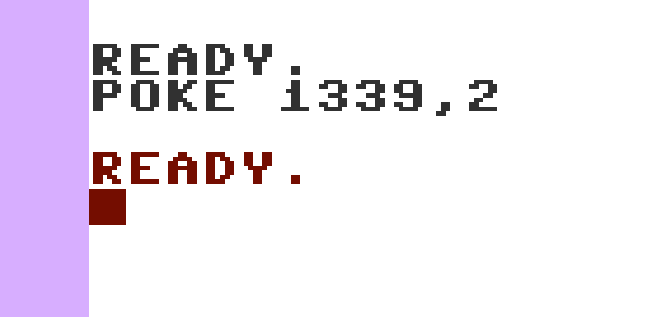
Continuing execution of the program will result in blank screen? What gives? Ah… Remember the program set the background and ink colour to Black? That’s why…
You can either press CTRL+2 to change the INK colour or POKE 1339,2
The listing displays a simple Splash Screen and continues to LOAD the next program into memory.

But wait? it’s BASIC LOAD so why is it able to turbo load the game portion? Remember earlier in the code the ILOAD Indirect Vector was patched? Addresses $32E/$32F contain the actual address the Kernel requires to LOAD data. This was updated to point to the turbo loader at address $0333. The beauty of this meant that game developers and producers didn’t need to modify the original game code to account for the turbo and protection system implementations, allowing them to focus on writing games and not worrying about accommodating changes to original code!

The game code loaded as expected, however if you try to LIST the program you may encounter an out of memory error since the game code loaded to the top of memory at $3FFF on an unexpanded C16.

(C:$d90c) m $1001
>C:1001  0b 10 00 00  9e 36 39 30   .....690
>C:1009  30 00 00 00  00 00 00 00   0.......
If you type RUN the game will start as expected, though you’ll be wanting to know the actual start address of the game.
Enter monitor mode again and DUMP the memory at address $1001 – Start of BASIC
It’s obvious here that the start address is 6900 (decimal) $1AF4 but let’s break that down.
The first two bytes point to the next address of the next line of the BASIC program ($100B)
The next two bytes ($00 $00) is the BASIC Line number, in this case LINE 0
The remaining bytes are the BASIC command. SYS is tokenised as $9E followed by the address 6900
Every line is terminated with a NULL byte, and end of program is terminated with double NULL bytes.
Brief Recap
The short version is the NOVALOAD system overwrites the system stack when loading the initial block of data to force execution of the loader code without user intervention and try to fool crackers of the day into giving up!
The loader payload was stored in both the DATA portion of the cassette block AND the Cassette HEADER. Pretty ingenious for something in the early 80’s
NOVALOAD Contained a few basic checks to prevent tampering, resulting in the program wiping itself from memory.
It also fulfilled the brief of significantly improving loading times for games of the day and more beneficial than the default Kernel provided routines.
How Do We Bypass this Protection System
Every hacker security engineer develop their own techniques and tricks, you may want to write a routine to force loading the code to different memory address and that will work quite well. I’m still rusty compared to my skills back in the 80s on this machine, however I found that the Kernel routines refused to relocate/load the data at the address I specified. Maybe because I’m not addressing the ROM correctly? I’m sure smarter C16 users will remind me know how to achieve this.
My approach, and pretty much the same approachI used back in the 80s was (I believe) elegant and worked without relocating any of the original code on load. How? By simply shifting the Stack Pointer to below the start of Loader code to $13F
You can find the full code available on my Git Repository for Commodore Projects: https://github.com/muckypaws/RetroCheats
*=$3000
;
; Preserve Original stack
;
     SEI               ; Disable Interrupts
     STA     RestoreA+1
     STX     RestoreX+1
     STY     RestoreY+1; Preserve A,X,Y Registers
     TSX               ; Save SP to X
     STX     stack     ; Store Stack Pointer In Memory
     LDY     #$00      ; Set Offset Counter to 0
stackSave
     lda     $100,x    ; Get Stack Data
     sta     StackData,y ; Preserve Stack Data
     iny               ; Increment Y Offset
     inx               ; Increment X Stack Offset
     CPX     #$00      ; Has X Reached 0?
     BNE     stackSave ; Loop Until Stack Contents Saved
;
; Set Stack Below Novaloader Code
;
     LDX     #$3f      ; Set Stack Pointer to $3F
     TXS               ; Move X-> SP
;
; Now Load Code
;
     LDA     #$01
     LDX     #$01
     LDY     #$FF
     JSR     $FFBA     ; Set LFS
     LDA     #$00
     JSR     $FFBD     ; Set Filename to 0
     JSR     $FFD5     ; Load the Code
;
; Patch the Loader
;
     LDA     #$4C      ; JMP Op Code
     STA     $19E
     LDA     #<RestoreCode
     STA     $19F
     LDA     #>RestoreCode
     STA     $1a0
     JMP     $203      ; Execute the Loader
;
; Restore original stack
;
RestoreCode
     SEI               ; Ensure Interrupts Still Disabled
     LDX     stack     ; Restore the original Stack
     TXS               ; Set SP to Original
     LDY     #$00      ; Y Offset into Saved data
stackRestore
     LDA     stackData,y
     STA     $100,x    ; Copy Stack Byte for Byte
     iny
     inx               ; Increment Offsets
     cpx     #$00      ; Check if we've looped to $00
     bne     stackRestore
     LDA     #$02
     STA     $53B      ; Set INK Colour to 2
RestoreA
     LDA     #$00
RestoreX
     LDX     #$00
RestoreY
     LDY     #$00
     CLI               ; Enable Interrupts
     rts
stack byte    00       ; Byte to Store Original Stack Pointer
stackData
In it’s simplest form this code :-
Preserves the Stack and Registers, Sets the Stack Pointer below the code load location, LOADs the NOVALOAD Code in at address $140 as per the header, Patches the NOVALOAD to return control to our patch which
- Disable Interrupts.
- Preserve the registers A, X and Y into self modifying code.
- Preserves the System Stack contents from Current Stack Pointer (Usually $F6) thru to $1FF.
- Set the Stack Pointer to $3F ($13F In memory).
- Use the Kernel to Load the NOVALOAD Code to Memory in it’s original location.
- Patch the Loader to return control to our Code when the loader has loaded the next program (Usually a BASIC Loader).
- Starts the NOVALOAD System at $203.
- Control is returned to our program.
- Set the INK Colour to 2 – To show the cursor when control returned.
- Disable Interrupts Again
- Restore the Stack contents to its original location.
- Restore the Stack Pointer
- Restore the registers A, X and Y
- Enable Interrupts
- Return control back to BASIC or the caller of the patch routine.
10 rem novaload by pass (c) jason brooks
20 sa = 12288
30 for n = 0 to 98
40 read a% : poke sa+n,a%: next n
50 sys sa
60 end
70 data 120,141,91,48,142,93,48,140
80 data 95,48,186,142,98,48,160,0
90 data 189,0,1,153,99,48,200,232
100 data 224,0,208,244,162,63,154,169
110 data 1,162,1,160,255,32,186,255
120 data 169,0,32,189,255,32,213,255
130 data 169,76,141,158,1,169,66,141
140 data 159,1,169,48,141,160,1,76
150 data 3,2,120,169,2,141,59,5
160 data 174,98,48,154,160,0,185,99
170 data 48,157,0,1,200,232,224,0
180 data 208,244,169,0,162,0,160,0
190 data 88,96,0
This is the basic type in which implements the code above. If you want the code to work at a different address you’ll need to re-assemble the final code using CBM Program Studio.


What Now?
Hopefully the above information will give you the general idea of how the protection system works and how to bypass it for your own needs, whether it’t to learn or patch an original cassette. It’s really for information since emulation these days means we can halt program code and modify it relatively easily. This gives you an idea/flavour of how we tackled protection systems back in the 80s.
I have to appreciate the skill and efforts of the original developers of this system since the tools we had available were extremely basic at best, usually having to develop our own to work a problem.
In the next section we’re going to delve right into the actual Speed-loading code itself and how it reads data from cassette into memory. I’m impressed with the tightness of the actual Speed-loading code itself.
Again you can find the latest up to date information on my Git Repo: https://github.com/muckypaws/RetroCheats
The Loader Code at $0333
The real Speed Load code is located at $333, I’ve disassembled it and annotated the code as I’ve interpreted it, it may be subject to change which will be on my Git repo. The full code is below and we’ll work on breaking it down, as it’s quite tight and optimised pretty well, I’m unsure any further bytes could be squeezed out of this loader, though nearly 40 years later there may be a trick or two up some gifted coders sleeve!
$0333  A6 AE       LDX $AE			; $AE = Flag for NOVA Load Installed
$0335  E0 01       CPX #$01			; If Set to 1, all good and NOVA Load used.
$0337  F0 03       BEQ $033C		; Checks if Nova Load Vector Initialised
$0339  4C 4A F0    JMP $F04A		; If Not, Use the original Kernel LOAD  Routine
$033c  78          SEI				; Disable Interrupts
$033d  20 1B E3    JSR $E31B		; Displays "Press Play on Tape" and Waits for PLAY button to be pressed.

$0340  D8          CLD				; Clear Decimal Flag
$0341  A0 00       LDY #$00			; Reset to Zero
$0343  84 01       STY $01			; IO Port Last Port Read/Reset
$0345  8C 3F FF    STY $FF3F		; RAM Select BANK 0
$0348  84 A2       STY $A2			; Bytes to READ = 0 / 256
$034a  84 A1       STY $A1			; Integrity Check = 0
$034c  20 C7 03    JSR $03C7		; Read Cassette Data looking for Header Start
$034f  10 FB       BPL $034C		; Whilst Bit 7 = 0 Continue looking for a 1 Bit.
$0351  20 C5 03    JSR $03C5		; Read one Byte of Data from Cassette
$0354  C9 AA       CMP #$AA			; Is it #AA - Header ID?
$0356  D0 F4       BNE $034C		; No? Keep Looping until found.
$0358  20 C5 03    JSR $03C5		; Read Full Byte of Data from Cassette
$035b  C5 AB       CMP $AB			; Compare #$04 Set in init code (Length of Filename)
$035d  D0 ED       BNE $034C		; Sequence not #AA #04 then start again.
$035f  C4 AB       CPY $AB			; Has Y Reached end of Loop? 4
$0361  F0 0A       BEQ $036D		; If yes - Then Read Program Data
$0363  20 BE 03    JSR $03BE		; Read Next Byte
$0366  D1 AF       CMP ($AF),Y		; Compare next four bytes with $225 ($AF = $52 $02) - "NOVA"
$0368  D0 D7       BNE $0341		; If not header ID then continue looking for header.
$036a  C8          INY				; Y = Y + 1
$036b  D0 F2       BNE $035F		; While Y <> 0 Continue Reading Header
$036d  A0 FA       LDY #$FA			; Only need 6 bytes for Data Info
$036f  20 BE 03    JSR $03BE
$0372  99 A1 FF    STA $FFA1,Y		; Writes to $9B ->$A0 - Header Information
$0375  C8          INY
$0376  D0 F7       BNE $036F		; Loop until Y == 0
$0378  20 BE 03    JSR $03BE		; Read Next Bits
$037b  C5 A1       CMP $A1
$037d  D0 1F       BNE $039E		; Quit Routine and Cleanup
$037f  A5 A0       LDA $A0			; Block Number Currently Loading
$0381  8D 19 FF    STA $FF19		; Set Border Colour to Blocks
$0384  F0 1A       BEQ $03A0		; If Block == 00 jump 3A0 (Finished Loading)
$0386  E6 9C       INC $9C			; Increment MSB of Memory Load Location
$0388  C6 A0       DEC $A0			; Number of Blocks Remaining
$038a  D0 06       BNE $0392		; Load Block of Memory
$038c  A5 9F       LDA $9F			; Remaining Bytes to Read 1 - 255
$038e  F0 10       BEQ $03A0		; Finished Loading
$0390  85 A2       STA $A2			; Store Final Number of Bytes to Read.
$0392  20 BE 03    JSR $03BE		; Start Block Load
$0395  91 9B       STA ($9B),Y		; Y Contains Byte to Write
$0397  C8          INY				; Reached Y? Either EOF or 256 Bytes?
$0398  C4 A2       CPY $A2			; Reached the number of Bytes to Read?
$039a  D0 F6       BNE $0392		; If not continue reading Bytes
$039c  F0 DA       BEQ $0378		; Loop Back for Next Header and Continue Load Sequence
;
; Forced Delay to allow Tape to overrun a smidge (GAP) before stopping the
; motor and returning control to the caller.
;
$039e  A9 30       LDA #$30
$03a0  85 90       STA $90			; Kernel IO Status
$03a2  A9 05       LDA #$05			; Delay Loop before switching motor off
$03a4  CA          DEX
$03a5  D0 FD       BNE $03A4
$03a7  88          DEY
$03a8  D0 FA       BNE $03A4
$03aa  E9 01       SBC #$01
$03ac  10 F6       BPL $03A4		; Just Wasting Cycles
;
; Switch Tape Motor Off, Returning control with X/Y = Last Byte of Data Written
;
$03ae  A9 88       LDA #$88
$03b0  85 01       STA $01			; PORT I/O
$03b2  8D FC 07    STA $07FC		; Motor Lock
$03b5  8D 3E FF    STA $FF3E		; ROM Select
$03b8  A6 9D       LDX $9D
$03ba  A4 9E       LDY $9E			; $9D/9E = Last Byte Stored from Loader
$03bc  58          CLI				; Enable Interrupts
$03bd  60          RTS				; Return to Caller


$03be  18          CLC				; Clear Carry
$03bf  A5 A1       LDA $A1			; Integrity Check
$03c1  65 A7       ADC $A7			; Last Read Byte
$03c3  85 A1       STA $A1			; Store next result
$03c5  A9 7F       LDA #$7F			; Start of Bit Loading %01111111
$03c7  48          PHA				; Preserve A
$03c8  98          TYA
$03c9  48          PHA				; Preserve Y on stack
$03ca  AD 19 FF    LDA $FF19		; Get Current Border Colour
$03cd  49 7F       EOR #$7F			; Invert bits 0-6
$03cf  8D 19 FF    STA $FF19		; Write Border Colour To Screen
$03d2  A2 8F       LDX #$8F			; TED Timer 2
$03d4  A0 01       LDY #$01			; TED Timer 3
$03d6  A9 10       LDA #$10			; A = %0001 0000
$03d8  24 01       BIT $01			; Read Input Register
$03da  F0 FC       BEQ $03D8		; While Bit 4 = 1 Loop
$03dc  24 01       BIT $01			; Read Input Register
$03de  D0 FC       BNE $03DC		; Looking for Bit Toggle 1->0 on Bit 5
$03e0  AD 03 FF    LDA $FF03		; TED Timer
$03e3  8E 02 FF    STX $FF02		; Write $8F to Register - Timer 2
$03e6  8C 03 FF    STY $FF03		; Write $01 to register - Timer 3
$03e9  0A          ASL A			; Set Carry Flag With Timer 3 (1 or 0 bit)
$03ea  68          PLA				;
$03eb  A8          TAY				; Restore Y from the stack
$03ec  68          PLA				; Restore A from stack
$03ed  6A          ROR A			; Rotate Bits Right - Bit 0 -> Carry
$03ee  B0 D7       BCS $03C7		; If Carry Set Rinse and repeat.
$03f0  85 A7       STA $A7			; Otherwise Store A in $A7
$03f2  60          RTS				; Return Control
Remember the ILOAD Vector was updated to point to $0333 The turbo loader?
$0333 – $0339 Checks to see if the Turbo Loader is enabled via a Flag at $AE, if it’s not set to the value 1 then the loader returns control to the Kernel Load Routine at $E31B, doing so will of course destroy the NOVALOAD system as it resides in the Tape Buffer which will be overwritten by the Kernel.
$33C, The start of the real loader code.
$33C – $34A Initialises the Loader
- Disables Interrupts
- Display the “Press Play on Tape” Message and Wait for PLAY to be pressed (If it’s not already).
- Resets the DATA PORT at $01 (Writes 00)
- Set the RAM Bank to 0 (This is for PLUS Users or Memory Expansion Packs installed) to ensure the program loads into main memory only.
- Resets the Last Byte Read from Cassette and Integrity Check Byte to Zero.
$34C-$378 Checks for the Tape Header Data.
- Read a Bit from the Cassette Port and Search for BIT 1, Continue Looping whilst 0 Bits read.
- At this point the cassette is spinning up waiting to reach speed, data read on the port will be random using a real device at this point.
- The loop is waiting for it’s first hit on a 1 Bit Signal, which we’ll go into detail later.
- Read One Full Byte from the Cassette Port
- Check the Byte Read is $AA or %10101010
- This represents a “Pulse Train” used to help calibrate the binary 1’s and 0’s read from the datasette and to ensure the datasette is up to speed. The authors could have used any byte identifier, though if you’ve studied networking at the electrical signal level back in the 80s you’ll recognise pulse trains are very common methods for training and syncing signals.
- If the Byte read wasn’t $AA we loop back to the beginning at $34C to search for another 1 Bit on the Datasette port.
- Another Byte is read from the Datasette, this time looking for the Value $04 which is the length of the filename “NOVA”
- If the Sequence $AA $04 is not found (The File Header) then we loop back to beginning at $34C and repeat the process. The idea being that sometimes errant data as the datasette is speeding up could match one byte, two bytes less likely.
- The next few instructions between $35F and $36D check to see if Y = $04 (Length of the filename)
- Y is Incremented if the subsequent bytes read match “NOVA”, if not the counter is reset to 0 by looping back to $34C to continue looking for the header.
- This helps mitigate reading data mid datablock to a large extent, of course as long as the program code doesn’t match the same sequence and the tape happened to be fast-forwarded to that exact location.
- Essentially the entire Tape Header consists of the following six byte.
- $AA $04 “NOVA”
- Next up Six bytes are read which consist of the Tape File Information.
- The Developer sets Y = $FA
- Incrementing Y results in a six times loop until Y = 0
- Data Read is stored at $FFA1,Y
- Since the data is indexed by Y, the real location written to is $9B->$A0
- During each Byte READ, A sanity check is performed to ensure integrity of the last byte read against the previous bytes, a kinda poor mans CRC if you will. If the check fails, the program self-destructs.
- The NOVALOAD Tape Info Header information is shown in the table below.
| Byte | Usage |
|---|---|
| $9B/$9C | Data Location Vector (Where to write data) |
| $9D/$9E | Last Byte Loaded Address |
| $9F | Number of Bytes Remaining in the Block, 0-255 Bytes |
| $A0 | Number of Blocks to Load |
$378-39C Check if Code Finished Loading
- Check the Contents of $A0 to see if we’re at Block 0
- Set the Screen Border Colour to the Block Number
- If Block 0 Jump to $3A0 to start the code up.
- If not Block 0
- Increment the MSB of the Tape loading address at $9C
- Decrement the number of blocks left to load at $A0
- Check remaining bytes to read
- If Zero, then start the code up at $3A0
- Otherwise store the remaining bytes in $A2 to read
- A loop is performed to continually load data and store at address vector ($9B) until all block bytes are read.
- Loop to $378 to continue load process.
$39E-$3BE – Cleanup, Waste Cycles, Stop the Datasette Motor
- This section is probably the easiest of the Turbo Loader mechanism. It switches the Kernel IO Status to completion, and sets up loop to add a delay of around 1 second before switching off the Datasette Motor.
- X and Y contain the last address data was loaded.
- Interrupts are re-enabled
- Control is returned to the called or the tape loader, whether it was BASIC or Assembler language.
The Actual Loader.
That’s a lot of information to digest, plus this is the basics of the tape loader at a higher level, but… wait… there’s more!
The code needs to recognise which signals from the Datasette are 1’s and 0’s. We’ll break that down, though to help NOVALOAD utilised a neat trick from the C16 TED Chip. There’s a set of counters that continually count down located at $FF00 – $FF06. Two of these at $FF02 and $FF03 are meant for user utilisation.
You guessed it, these counters are set and used to time the length of 1 and 0 signals. For illustrations, a very crude diagram below, shows a “Perfect” signal over time and a voltage read on the Datasette Port. If you had an oscilloscope you would see a slant in the rise from 0v to 3v and an overshoot (Noise) from the datasette circuitry.

The code sets the user time to 399 which will continually count down on each cycle, for PAL machines 884Khz and NTSC Machines at 894Khz.
The developers had to take this variance into consideration. A Zero bit (The time between a rise and fall of the Signal from 0 to 1 to 0) needs to be less than 400 cycles, a 1 Bit will take more than 400 cycles of the counter. This results in a 1 Bit Duration forcing the TED Clock Timer to cycle backwards from $0189 -> $Fxxx

The trick is now simple, read the MSB of the Timer and shift the BIT7 into the Carry Flag. If the Timer took less, then the Carry Flag is Reset, and if it took longer, the Carry is set. I.e. $00 or $01 in $FF03 results in Carry Not Set, and $FF results in Carry Set.
The final trick is to rotate the carry flag into the data register for all eight bits before returning a full byte back.
Make sense?
Let’s take a look at the final leg of code.
The Actual Bits READ Routine
The main loader called different parts of the loader routine depending on whether it was looking for a Bit 1, Read a whole single byte, read a whole byte and update the integrity check byte as follows :-
$3C7 – Read the next BIT of data
$3C5 – Read a byte of data
$3BE – Read A Byte of Data and update the Integrity Check
$03be  18          CLC				; Clear Carry
$03bf  A5 A1       LDA $A1			; Integrity Check
$03c1  65 A7       ADC $A7			; Last Read Byte
$03c3  85 A1       STA $A1			; Store next result
$03c5  A9 7F       LDA #$7F			; Start of Bit Loading %01111111
$03c7  48          PHA				; Preserve A
$03c8  98          TYA
$03c9  48          PHA				; Preserve Y on stack
$03ca  AD 19 FF    LDA $FF19		; Get Current Border Colour
$03cd  49 7F       EOR #$7F			; Invert bits 0-6
$03cf  8D 19 FF    STA $FF19		; Write Border Colour To Screen
$03d2  A2 8F       LDX #$8F			; TED Timer 2
$03d4  A0 01       LDY #$01			; TED Timer 3
$03d6  A9 10       LDA #$10			; A = %0001 0000
$03d8  24 01       BIT $01			; Read Input Register
$03da  F0 FC       BEQ $03D8		; While Bit 4 = 1 Loop
$03dc  24 01       BIT $01			; Read Input Register
$03de  D0 FC       BNE $03DC		; Looking for Bit Toggle 1->0 on Bit 5
$03e0  AD 03 FF    LDA $FF03		; TED Timer
$03e3  8E 02 FF    STX $FF02		; Write $8F to Register - Timer 2
$03e6  8C 03 FF    STY $FF03		; Write $01 to register - Timer 3
$03e9  0A          ASL A			; Set Carry Flag With Timer 3 (1 or 0 bit)
$03ea  68          PLA				;
$03eb  A8          TAY				; Restore Y from the stack
$03ec  68          PLA				; Restore A from stack
$03ed  6A          ROR A			; Rotate Bits Right - Bit 0 -> Carry
$03ee  B0 D7       BCS $03C7		; If Carry Set Rinse and repeat.
$03f0  85 A7       STA $A7			; Otherwise Store A in $A7
$03f2  60          RTS				; Return Control
We’ll go through this line by line, starting at the very top, read a whole byte and update the Integrity Check Byte.
- Clear the Carry Flag
- Get the contents of $A1 – Integrity Check Byte
- ADD the last byte read from that datasette, and store it back in $A1
- Load the Bit Pattern %01111111
- The way the loop is constructed this will actually load all 8 bits of data using the final bit to know the byte load is complete.
- Push A and Y onto the Stack.
- A Contains both the actual byte read and the number of bits remaining to load!
- Y contains the number of bytes remaining to read, not used here but preserved for the higher level loader.
- Get the current Border Colour and Inverse the lower 6 bits, writing back to the Screen Border Colour Register
- This gives you the flashing border you’re familiar with.
- X, Y and A are initialised.
- X = $8F the LSB of the TED Timer
- Y = $01 the MSB of the TED Timer
- The ted Timer will be set to 399 however 400 cycles is required to count down to $FFFF
- A is set to Bit 4 High the register we’re interested in reading from $01 – Datasette Signal.
- The code sits and waits checking the following
- While Bit 4 of $01 is set, loop until it becomes 0
- While Bit 4 of $01 is not set, loop until it becomes a 1
- This essentially wastes cycles looking for a complete rise and fall signal from the datasette.
- Read the contents of the MSB of the TED Timer.
- Reset the TED Timer to contain the count 399
- Left Shift the Accumulator, basically BIT 7 is transferred to the Carry Flag which gives us the BIT 0 or BIT 1 read from cassette.
- Restore the original Accumulator and Y register.
- Rotate Right the Accumulator which contains the number of bits remaining to load, and the actual bit read from cassette into BIT 7.
- Carry is shifted into BIT 7 and Bit 0 is shifted into Carry
- We’ll loop seven more times to complete the load, since the original mask %01111111 will result in CARRY Not Set on the eight final read.
- Loop back to $3C7 to continue reading bits until the byte is complete.
- Store the result in $A7
- Return control to the caller.
Now that’s quite a lot to take in! Given there’s a lot going on, in a few bytes of code, I do recommend tracing this routine yourself using a modern emulator. Trying to go old-school on a real device will result in overruns as the tape will continue moving whilst you’re debugging.
Added Bonus!
If you’ve made it this far, and you too are a fan of Mr Puniverse, then I worked out a couple of cheats for you!
Infinite Air: POKE 13159,29
Or in Monitor Mode
> $3367 $1D
Infinite Lives: POKE 13327,13
or in Monitor Mode
> $33AB $0D
That’s all Folks!
There’s a lot of info here, if you spot an error, or area that needs clarification, why not drop me a line on the contact page or in the comments below. If you’d like more articles like this, then let me know.
I hope you found this useful, if you did please share the link on social media, via email and help spread the word, every little helps as they say.
Thanks for reading.
Jason x
Yeah it’s begging season, without your support maintaining this site is a hobby, but if you found this article useful, why not spot me a coffee?
Choose an amount
Or enter a custom amount
Your contribution is appreciated.
Useful Memory Addresses used by NOVALOAD.
$01          Data Read on PORT
$9B/$9C      Code Load Location Vector
$9D/$9E      Last Byte Load Location
$9F          Remaining Bytes to Read
$A0          Number of Blocks to load
$A1          Integrity Check, storing last byte read and adding that to next byte,
$A2          Number of Bytes to read - 00 = 256
$A7          Last Byte Read
$AB          Length of Filename - Typically 4, Filename = "NOVA"
$AE          NOVALOAD System loaded FLAG 1 = NOVALOAD
$B6/$B7      Tape Buffer Location, Usually Contains $0333
$100->$10F   Floating Point Conversion Buffer
$110->$112   Temp Locations for Saving Registers during File Operations
$114->$122   Colour/Luminance RAM Table
$124->$1FF   System Stack
$333->$3F2   Tape Buffer
$333/$334    First Byte of Payload Address
$335/$336    Last Byte of Payload Address
$337         Filename and remaining Buffer
$53B         Current INK Colour (Cursor/PEN)
$1001        BASIC Load Address (Typically)
