
µPD765A Disc Controller – Primer
Back in the 80’s, Disk protection systems were starting to evolve at a rapid rate, presumably due to the use of IBM PC’s, Amiga/Atari STs on the market that could do a lot more with the controller than had been implemented on the target hardware. These machines were beasts in comparison, having more memory and could cross compile to multiple target machines with ease, making development of games and tools more efficient and streamlined. The PDS (Programmers Development System) was an expensive bit of kit, way out of my price range (Starting at around £2K). https://retro-hardware.com/2019/05/29/programmers-development-system-pds-by-andy-glaister/
Whilst using documented and undocumented AMSDOS ROM commands got you so far, understanding and fully controlling the µPD765A controller became necessary.
A friend back then “Dave” had access to all sorts of hardware documentation. One morning on his way to work, he dropped off a bundle of documents including hardware/circuit diagrams for the Amstrad CPC computer range, service documents and the µPD765A specification. Stuff I couldn’t get hold of myself.
I set to work reading the documentation, learning about Microelectronics at school helped enormously. From about the age 10, I was no stranger to a soldering iron and PCBs. The article below is the result of my own work back in the late 80s, using code from my original three inch disks. This will serve as a simple primer before I write up how I went about developing hacks for old school disk protections systems, some fo which went into commercial tools with Goldmark’s Nirvana+ and Nemesis Bonzo Pack for Sector #48, 6K Sectors and more.
Please Note
This article is a Primer only, to cover the basics. I will be following up with write ups of other FDC Commands such as Track Read which I took advantage of to create a Disk Protection System JaceLock, and more.
My Git Hub Repo containing my legacy disks and source code (Still to be sorted), is found here: https://github.com/muckypaws/AmstradCPC
The source code for this write up can be found: –https://github.com/muckypaws/AmstradCPC/blob/master/Assembly/DDFDC/DDFDC_MK2.asm

Thank you for taking the time to read my Blog.
If you would like to support me and my work, please check out my Online Store: www.muckypawslabs.com alternatively…
We all know developers and coders run on Coffee…
Choose an amount
Your contribution is appreciated.
What do you need?
The article is technical in nature, and may be rough on the novice or beginner starting out to understand the history behind this… That said, you’re here so, please stick with it, it will make sense (Eventually), and I’m not the best at explaining tech stuff in layman terms, therefore constructive feedback is always welcome, or share your own experiences when coding for this tech. We all approach problems from differing angles.
- You’ll need some Z80 Assembler Knowledge and Skills.
- A development Environment
- I use ADAM IDE for the Amstrad CPC, though JavaCPC contains a built in developer environment for assembly and disassembly to practice.
- The µPD765A Specification.
AMSDOS ROM
The AMSDOS ROM, was quite advanced for the home computer market. Under the covers the developers enabled you to achieve a lot in terms of reading, writing and manipulating disk data. In fact, most of what I present here can be achieved with the correct manipulation of the eXtended Disk Parameter Block (XPDB), either used undocumented routines built into the ROM, or created their own. DiscSys Protection system, is a prime example of this. The Author used their indepth knowledge of the AMSDOS Rom to create a Disk that couldn’t be copied using the existing CP/M Tools of the time. It had the advantage of code re-use, reducing the footprint of the loader code required.
I wanted more control. Learning to interface directly with the controller had advantages achieving more, but also a steeper learning curve if you’re not going to use what the system developers already provided you.
First Steps
There are a number of stages to enable access to the Disk and the Disk Controller, some of which needs carefully calculated timing. In addition some logical steps need to be taken. Going forward, I’ll break some of these down. Most operations require the Disk Motor to be spun up, running at the correct speed, Some Operation/Command to execute, and Stop the Disk Motor when all operations are complete.
I’ll go through the following :-
- STOP / START the Disk Motor
- Command Phases
- Recalibrate (Move to Track 0)
- Seek
- Read a Sector
- Write a Sector
- Format a Track
- How the start of Track is known.
- Full Source Code
- Appendix of Status Registers.
MOTOR ON/MOTOR OFF
The Amstrad CPC implements access to the Disk Controller via Ports #FA7E and #FB7E.
Switching the Drive Motor ON/OFF is simply a case of using these BASIC commands :-
OUT &FA7E,1 : REM Switch the Drive Motor ON
OUT &FA7E,0 : REM Switch the Drive Motor OFF
Try it and see for yourself.
In assembler, i created the following in my DDFDC Library. It does a bit extra like preserve registers and adds a delay to wait for the drive to start spinning up to speed. You can achieve the same in much fewer bytes as you’ll see further down.
Motor On/Off Code Snippet
motoron
         DI                             ; All Reg. Preserved
         PUSH hl
         PUSH bc
         PUSH af
         LD   bc,#fa7e
         LD   a,1
         OUT  (c),a
         LD   hl,0
         LD   b,2
motoron1                                ; Pause Loop To Allow Motor To Pick Up
         DEC  hl
         LD   a,h
         OR   l
         JR   nz,motoron1
         DJNZ motoron1
         POP  af
         POP  bc
         POP  hl
         RET                            ; Exit All Reg. Preserved
motoroff
         PUSH bc
         PUSH af                        ; All Reg. Preserved
         LD   bc,#fa7e
         XOR  a
         OUT  (c),a
         POP  af
         POP  bc
         RET                            ; Quit All Reg. Intact
A few more commands than BASIC, you can shorten it to :-
motoron
        LD A,1
motorctl
        LD BC,#FA7E
        OUT (C),A
        RET
motoroff
        XOR A
        JR motorctl
The first motor on routine sets a delay loop to give the drive to spin up to speed. Amstrad CPC Drives are expected to spin at approximately 300 rpm, though the controller IC allows some variable tolerance of around +/- 10%.
That’s the easy bit!
Drive Command Phases
The µPD765A Controller typically uses three phases of command to complete command execution. There are some commands that don’t have a results phase, or an execution phase. These are shown in the Specification, but I’ll cover the common scenario’s here.
- Command Phase
- Execution Phase
- Read Data
- Write Data
- Results Phase
These phases are documented in the µPD765A Controller specification, though they’re not the most user friendly explanations… looking back I now realise how technical these documents are… As a teenager they seemed straight forward, nearly 40 years later I’m having to re-read/re-learn all over again.
Before going into each of the commands, I’ll describe the code I write in the 80’s to implement the interface to the controller.
Command Phase
Each of the phases of the controller are time critical, requiring 13µs pause between each command and parameter issued. You can jump to the code below which shows how I approached the problem.
Port #FB7E is used to Read the Main Register of the Disk Controller. #FB7F is used to READ/WRITE data to the Controller. To make it easier, The LD DE,command_table is a simple pointer to a table of commands and parameters.
The first byte in that table will be the number of commands needed to send. The flowchart below shows what’s going on in the code. For example, the Recalibrate command requires two parameters to be passed to the controller, #07, #00, where #07 is the command and #00 is the drive number and head we want to recalibrate. The table contains a length byte (#02) at the start, it’s used to tell our code we’re passing two bytes of data.
;
;                 **** COMMAND DATA FOR RECALIBRATE ****
;
RECALCOM DEFB 2                         ; 2 Parameters
         DEFB 7                         ; Command Code For RECALIBRATE
         DEFB 0                         ; Which Drive
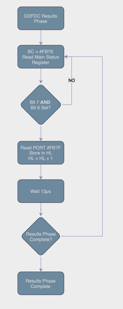
It’s probably easier to show the flow of the Command Phase to help understand the code.

We need to ensure the controller is ready to receive our commands. To achieve this, we read the Main Status Register using A = INP(#FB7E), using the IN A,(C) assembler command.
We test the value of Bit 7 and Bit 6 using a simple ADD A,A command.
ddfdc1                                  ; Is Drive Ready To Accept Command ?
         IN   a,(c)
         ADD  a,a
         JR   nc,ddfdc1
         JP   m,ddfdc1                  ; If Not Then Wait
Why? We need to look at the Main Status Register from the controller.
- Bit 7 (RQM – Request for Master) is set to 1 when ready to receive data.
- Bit 6 (DIO – Data Input/Output) is set to 0 when in READ mode, 1 if Write mode.
We could just test bit 7 and bit 6 individually, or compare to a value #80… but remember we’re in tight time critical code, and this is a more elegant solution.
ADD A,A is the same as A = A * 2, the Carry Flag will be Set if an overflow condition occurs. For example #80 or 128 results in the answer 256. The accumulator will become #00 and the Carry Flag will be Set to indicate there’s more to the answer. In addition, Bit 7 is also used to indicate a negative number.

If the data read from the Main Status Register has Bit 7 = 0, then Carry will not be set regardless of the other bits, so we continue reading until Bit 7 is set. I.e. any original value less than 128 of #80 when doubled can not be greater than 254.
#80 * 2 = #100, A = #00 and Carry is Set.
We need the Controller to be in Ready for READ Mode, (Ready to READ OUR COMMANDS – Transfer from Processor to Data Register) hence Bit 6 must be 0 or reset. The ADD A,A also checks this for us? How?
The JP M,ddfdc1 command. This means the S – Sign Register is set, meaning Bit 7 is now set. Bit 6 = #40, #40 * 2 = #80.
Check this for your self… By experimenting with the code below in your assembler and monitor program.
        ORG #A000
start
        ENT $
        LD A,#80
        ADD A,A
        RET NC                ; Carry Always Set
        LD A,#40
        ADD A,A
        RET M                ; Always return as A=#80 Sign is Set
        LD A,#C0
        ADD A,A
        JP M,start        ; Won't be reached without changing A above
If the main status register = #Cx (RQM and DIO) set, then both Carry and Minus will be set, we continue to loop until the Controller is ready to Receive our Commands. Clever eh? and all in six bytes.

Code Fragment for the FDC Command Phase
;
;                        **** DDFDC COMMAND PHASE ****
;                        DE = Command Table Data
;
ddfdccom                                ; DDFDC Command Phase
         LD   bc,#fb7e
         PUSH bc
         LD   a,(de)                    ; Get Number Of Parameters
ddfdc
         PUSH af                        ; Preserve Counter
         INC  de
ddfdc1                                  ; Is Drive Ready To Accept Command ?
         IN   a,(c)
         ADD  a,a
         JR   nc,ddfdc1
         JP   m,ddfdc1                  ; If Not Then Wait
         LD   a,(de)
         INC  c
         OUT  (c),a                     ; Give DDFDC Command @ Port #FB7F
         DEC  c
         LD   a,5
ddfdcp                                  ; Wait 13 uS
         DEC  a
         JR   nz,ddfdcp
         POP  af
         DEC  a
         JR   nz,ddfdc
         POP  bc                        ; On Return BC=#FB7E
         RET                            ; Quit
Execution Phase (Read/Write)
The command phase was fairly straight forward, the code simply waits for the state of the controller to be ready to receive our commands, then we send the command and the command parameters in sequence 13µs apart.
Depending on the FDC Command we’re invoking, the execution phase is either :-
- READ Data From the Controller. CALL ddfdcexc
- WRITE Data to the Controller. CALL ddfdcwri
We READ Data if we’re scanning Sector IDs, Sector/Track Data, Validating Data etc.
WRITE Mode would be for Formatting Tracks, Writing Sector information and so forth.
The code for the execution phase is fairly straight forward, we pass the Drive we want to access in the Accumulator (0 = Drive A, 1 = Drive B), we then OR this with #20 (The RQM Execution Mode Bit). And use Self-Modifying code to check that the Drive is still in execution phase for that drive later in the loop. HL is set to point to a location in memory where the data will be stored.
The loop simply checks the Drive status, and reads data from the PORT until the Controller signals there’s no more data to be read.

Equally when WRITING Data to the Controller, the logic is similar except we send data pointed to in HL until the controller signals to stop. It’s the easier phase.

Code Fragment for the FDC Execution Phase
;
ddfdcexc                                ; DDFDC Execution Phase - DATA IN
         LD   a,(drive)
         OR   #20
         LD   (ddfdexc2-1),a
ddfdcexd
         LD   bc,#fb7e
         IN   a,(c)
         CP   #c0
         JR   c,ddfdexc1
ddfdexc0
         INC  c                         ; Point To #FB7F - DATA REGISTER
         IN   a,(c)                     ; Get byte from port
         LD   (hl),a                    ; Store it
         DEC  c                         ; Restore Port To Main Status Reg.
         INC  hl                        ; HL+1
ddfdexc1
         IN   a,(c)
         JP   p,ddfdexc1                ; Drive Not Finished Output So Wait
         AND  #20                       ; Main Status Reg=Execution Phase Start
ddfdexc2
         JR   nz,ddfdexc0               ; If Not Finished Loop ddfdexc
         RET                            ; Else Quit
;
;              **** DDFDC EXECUTION PHASE DATA TO SYSTEM ****
;
ddfdcwri                                ; DDFDC Write Into Data Register
         LD   bc,#fb7e                  ; Point To MAIN STATUS REG
         LD   a,(drive)
         OR   #20
         LD   (ddfdcw3-1),a
         JR   ddfdcw2                   ; Wait Till DDFDC Ready.
ddfdcw1
         INC  c                         ; Point To Data Port
         LD   a,(hl)                    ; Get Byte To Place
         INC  hl                        ; HL+1
         OUT  (c),a                     ; Output To Port #FB7F
         DEC  c                         ; Restore Port
ddfdcw2
         IN   a,(c)
         JP   p,ddfdcw2                 ; If Drive Not Ready Loop ddfdcw2
         AND  #20
ddfdcw3
         JR   nz,ddfdcw1                ; Is All Output Finished ?
         RET                            ; Quit
;
The Results Phase
Finally we enter the results phase. The controller will send data informing us of the success or otherwise of the command we attempted to execute.
The code should start looking familiar now, as we add Bit 5 to the Drive number to check for readiness of the controller.
We also check the controller is both ready and the the DIO bit is set, a simple compare is all that’s needed here.
The results are written to a buffer pointed to in HL.
LD A,Drive
LD HL, Results_Buffer
CALL ddfdcres
The results buffer will contain information on the Drive Registers ST0, ST1, ST2, Track Number, Drive, Sector Number and Sector Size though these bytes are defined in the Specification.
Code Fragment for the FDC Results Phase
;
;                       **** DDFDC RESULTS PHASE ****
;
ddfdcres                                ; DDFDC Result Phase
         LD   a,(drive)
         OR   #10
         LD   (ddfdresq-1),a
ddfdcret
         IN   a,(c)
         CP   #c0                       ; Is DDFDC Ready ?
         JR   c,ddfdcret                ; If Not Wait
         INC  c
         IN   a,(c)                     ; Get Byte From DATA REG
         LD   (hl),a                    ; Store it
         DEC  c                         ; Restore Data Reg.
         INC  hl                        ; HL+1
         LD   a,5
ddfdresp                                ; Wait 13 uS
         DEC  a
         JR   nz,ddfdresp
         IN   a,(c)
         AND  #10                       ; Has Results Finished ?
ddfdresq
         JR   nz,ddfdcret               ; If Not Loop ddfdcres
         RET                            ; Quit
Putting it all together.
Now you have the assembly code basics for accessing the controller, it’s time to pull it all together and do something useful…
We need to implement some of the FDC Commands. Whilst many emulators do an awesome job of implementing Support, if you can try this on real hardware you will see some subtle differences. Mainly in the way the DSK File format masks some of the intricacies of Disk Formats and Status Codes, they will be predictable, physical and ageing disks won’t…
Recalibrate the Drive
Not quite what you may think here, this command doesn’t test speed or calibration of the stepper motors etc, it’s basically a way for the controller to know it’s start position after powering on your machine. Where is the drive head located now? Since the controller has no memory, it has no way of knowing which track it’s currently aligned to or if it moved after power off.
The recalibrate commands seeks to move the Drive Head to Track 0. A micro switch signals the controller the head is in the home position. From here on in, the drive will operate without the need to execute this command.
When Recalibrating the Drive Head, this is associated with the Sense Drive Status Command to ensure the operation is complete.
In likelihood, AMSDOS will have completed this task the moment you accessed a Disk in your Amstrad.
In all your disk operations you need to move the drive head up and down the disk to point to the correct track. There are a few steps you need to complete this.
- Set the Drive ID (0 – Drive A, 1 – Drive B)
- Set the Track you want to move to.
I’ve coded my library as follows.
- Is requested Track same as Current Track?
- If Yes, Quit no work to do.
- If Requested Track = 0?
- If Yes, issue the Recalibrate Command.
- Else Send SEEK Command
- Wait until the Sense Interrupt shows the operation is complete.

Below are the commands in easier to read format, compared to the PDF that’s available.
RECALIBRATE Command
The Recalibration command doesn’t have an execution or status command phase.
| Offset | Command | Definition |
|---|---|---|
| 0 | #07 | Recalibrate Command |
| 1 | #00 | The Drive number to Recalibrate |
SEEK Track Command
Whenever moving the Drive head to a different Track, you must always execute the SEEK command.
| Offset | Command | Definition |
|---|---|---|
| 0 | #0F | Seek Command |
| 1 | #00 | Drive Number, 0 = A, 1 = B, Bit 2 can be set if you have dual heads. |
| 2 | #00 | Destination Track, Usually 0 – 41, anything higher than this will likely damage the 3″ Disk Drive. If you have a 3.5″ Disk Connected, you can access higher tracks. |
SENSE INTERRUPT STATUS COMMAND
| Offset | Command | Definition |
|---|---|---|
| 0 | #08 | Sense Interrupt Status Command |
| Offset | Response | Definition |
|---|---|---|
| 0 | ST 0 | Status Register 0 Data – See Appendix |
| 1 | PCN – Present Cylinder Number | What is the current Track we’re on? |
SENSE DRIVE STATUS COMMAND
| Offset | Command | Definition |
|---|---|---|
| 0 | #04 | Sense Drive Status Command |
| 1 | #00 | Drive Number, 0 = A, 1 = B, Bit 2 can be set if you have dual heads. |
| Offset | Response | Definition |
|---|---|---|
| 0 | xx | Status Register 3 Data – See Appendix |
SEEK Track Code Usage
The snippet below shows how to invoke the movtrak command.
D = Track Number (0-41)
E = Drive Number (0 = A, 1 = B)
If Track 0 is requested the code will automatically perform a recalibration.
LD D,trackNumber
LD E,Drive
CALL movtrak
Seek, Recalibrate and Sense Drive Commands Code Snippet
;
;                        **** Move Drive Head To Track T ****
;
drivicl  DEFB 0
movtrak                                 ; On Entry D = Destination Track
         PUSH af
         PUSH bc
         PUSH de
         PUSH hl                        ; Preserve Registers
         LD   a,e
         OR   #20
         LD   (drivicl),a
         CALL senseint                  ; Get Current Track Position
         LD   a,(sense+1)
         SUB  d                         ; Is Destination Track Current Track ?
         JR   z,movtrake                ; If So Quit
         LD   a,d                       ; A = Track
         OR   a                         ; Is Destination Track 0
         JR   z,trak0                   ; If So Then Trak0
         CALL seek                      ; Give DDFDC SEEK Command
movtrak1                                ; Use This Since No DMA
         CALL senseint                  ; Has Drive Reached Destination ?
         LD   hl,drivicl
         LD   a,(sense)
         CP   (hl)
         JR   nz,movtrak1               ; If Not Loop movtrak1
movtrake                                ; Quit Routine
         POP  hl
         POP  de
         POP  bc
         POP  af
         RET                            ; Preserved Registers
trak0
         CALL recalib                   ; Recalibrate (Move To Track 0)
trak01
         CALL senseds                   ; Call SENSE DRIVE STATUS
         LD   a,(hl)
         AND  %10000                    ; Has Drive Head Reached TRK 0
         JR   z,trak01                  ; If Not Loop
         JR   movtrake                  ; Restore Regs & Quit
;
;                       **** SENSE DRIVE STATUS ****
;
senseds
         LD   a,(drive)
         LD   (SenseCde+2),a
         LD   de,SenseCde
         CALL ddfdccom
         LD   hl,sendst                 ; Pointer To Put Resultant Data
         CALL ddfdcres
         DEC  hl                        ; On Exit HL=Address Of Status Reg. 3
         RET                            ; Quit
;
;                  **** RECALIBRATE DRIVE HEAD (TRACK 0) ****
;
recalib                                 ; Recalibrate
         LD   de,RECALCOM
         LD   a,(drive)
         LD   (RECALCOM+2),a
         JP   ddfdccom
;
;                       **** SENSE INTERUPT STATUS ****
;
senseint                                ; Sense Interupt Status
         PUSH de                        ; Preserve DE
         LD   de,SENSE_INT
         CALL ddfdccom
         LD   hl,sense
         CALL ddfdcres                  ; Call & Quit
         POP  de
         RET
;
;                   **** SEEK COMMAND MOVE TRACK HEAD ****
;
seek                                    ; SEEK Entry D=Track
         PUSH de
         LD   (Seek_DT+3),a
         LD   a,(drive)
         LD   (Seek_DT+2),a
         LD   de,Seek_DT
         CALL ddfdccom
         POP  de
         RET
;
;            **** COMMAND DATA FOR SENSE DRIVE STATUS ****
;
SenseCde
         DEFB 2                         ; 2 Parameters
         DEFB 4                         ; Code For SENSE DRIVE STATUS
         DEFB 0                         ; Drive
;
;                   **** COMMAND DATA FOR SEEK ****
;
Seek_DT                                 ; Seek Codes For Command
         DEFB 3                         ; 3 Parameters
         DEFB 15                        ; Command For Seek
         DEFB 0                         ; Drive
         DEFB 0                         ; Destination Track
;
;            **** COMMAND DATA FOR SENSE INTERUPT STATUS ****
;
SENSE_INT DEFB 1                         ; One Parameter
         DEFB 8                         ; Command Code For SENSE INTERRUPT STATE
Reading Sectors
Now we have the “Basics” out of the way, you’ll be wanting to do something useful like Reading Data …
Thankfully this and other commands are straight forward.
The table located at readcomd contains all the information needed to read a sector, you need to set these parameters accordingly, helper function patchrwd attempts to do this for you.
READ Command
| Offset | Command | Definition |
|---|---|---|
| 0 | #46 | Read Sector Command from MFM Disk |
| 1 | #00 | Drive Number, 0 = A, 1 = B, Bit 2 can be set if you have dual heads. |
| 2 | #00 – #29 | Cylinder – Track Number to Read |
| 3 | #00 – #01 | Head Number, 0 = Drive A, 1 = Drive B |
| 4 | #xx | Sector ID to Read, i.e. #C1 for First Sector of DATA Format |
| 5 | #00-#05 | N – Sector Size 2^(7+n) |
| 6 | #xx | Last Sector ID to Read Sequentially. For example you could set it up to Read all sectors from #C4 to #C7 |
| 7 | #xx | GAP#3 Length |
| 8 | #FF | Data Length, if less than 255 bytes, change this to the amount you want to Read. |
| Offset | Response | Definition |
|---|---|---|
| 0 | ST 0 | Status Register 0 |
| 1 | ST 1 | Status Register 1 |
| 2 | ST 2 | Status Register 2 |
| 3 | C | Cylinder/Track Number |
| 4 | H | Head Number |
| 5 | R | Sector Number Read |
| 6 | N | Size of Sector Read 2^(7+N) |
It’s important to check the status of the registers after a read operation to check if completed successfully.
The command response is stored in readcomr, check the status to ensure all has gone as expected.
- Set HL to point to a memory location to load the sector.
- E = Drive Number
- D = Track Number
- C = Sector ID to Read
- CALL readsect
Read Sector Code Fragment
readsect                                ; ENTRY HL=BUFFER E=DRIVE D=TRK C=SECTR
         PUSH af
         PUSH bc
         PUSH de
         PUSH hl                        ; Preserve Registers
         CALL movtrak                   ; Move To Appropriate Track
         PUSH hl
         LD   hl,readcomd+2
         CALL patchrwd                  ; Patch Read Data
         LD   de,readcomd
         CALL ddfdccom                  ; Set Up Command
         POP  hl
         CALL ddfdcexc                  ; Get Bytes From EXECUTION PHASE
         LD   hl,readcomr
         CALL ddfdcres                  ; Get Result From Read Command
         POP  hl
         POP  de
         POP  bc
         POP  af
         RET
;
;             **** PATCH READ WRITE DATA FOR READ/WRITE COMMAND ****
;
patchrwd                                ; Patch Read Write Data
         PUSH hl
         PUSH af
         LD   a,e                       ; A=Drive
         LD   (hl),a
         INC  hl
         INC  hl                        ; Point HL To Head Number
         LD   (hl),a                    ; Store Head Number
         DEC  hl                        ; Point To Track Data
         LD   a,d                       ; A = Track
         LD   (hl),a                    ; Store Track Number
         INC  hl
         INC  hl                        ; Point To Sector
         LD   a,c                       ; A = Sector
         LD   (hl),a                    ; Store It
         INC  hl
         INC  hl                        ; Point To End Of Track
         LD   (hl),a                    ; Store Sector
         DEC  hl                        ; Point To Sector Size
         LD   a,(sectsize)              ; Get Sector Size From XDPB
         LD   (hl),a                    ; Store It
         INC  hl
         INC  hl                        ; Point To Gap Length
         LD   a,(gap3rw)                ; A = Gap #3 For READ/WRITE
         LD   (hl),a                    ; Store It
         INC  hl                        ; Point To Data Length
         LD   a,(dataleng)              ; A=Sector Length
         LD   (hl),a                    ; Store It
         POP  af
         POP  hl
         RET
;
;                 **** COMMAND DATA FOR READ SECTOR ****
;
readcomd                                ; Read Command Data
         DEFB 9                         ; 9 Parameters
         DEFB #46                       ; READ DATA Command Alter To #4C Del.
         DEFB 0                         ; Drive
         DEFB 0                         ; Track
         DEFB 0                         ; Head Number
         DEFB #C1                       ; Sector To Read
         DEFB 2                         ; Number Of Data Bytes Per Sector
         DEFB #C1                         ; End Of Track
         DEFB 0                         ; Gap #3 - Generally #2a
         DEFB #FF                       ; Data Length - Sect Size < 256
;
;        **** READ DATA RESULTANT BYTES FROM RESULT PHASE ****
;
readcomr                                ; Read Command Result Table
         DEFB 0                         ; Status Register 0
         DEFB 0                         ; Status Register 1
         DEFB 0                         ; Status Register 2
         DEFB 0                         ; Track Number
         DEFB 0                         ; Head Number
         DEFB 0                         ; Sector Number
         DEFB 0                         ; Sector Size
Writing Sectors
If you followed through the READ Sector code above you won’t be surprised how similar these routines are.
The command response is stored in writcomr, check the status to ensure all has gone as expected.
- Set HL to point to the memory location of the data to write.
- E = Drive Number
- D = Track Number
- C = Sector ID to Write
- CALL writsect
WRITE DATA COMMAND
| Offset | Command | Definition |
|---|---|---|
| 0 | #45 | Write Sector Command from MFM Disk |
| 1 | #00 | Drive Number, 0 = A, 1 = B, Bit 2 can be set if you have dual heads. |
| 2 | #00 – #29 | Cylinder – Track Number to Read |
| 3 | #00 – #01 | Head Number, 0 = Drive A, 1 = Drive B |
| 4 | #xx | Sector ID to Write, i.e. #C1 for First Sector of DATA Format |
| 5 | #00-#05 | N – Sector Size 2^(7+n) |
| 6 | #xx | Last Sector ID to Write Sequentially. For example you could set it up to Write all sectors from #C4 to #C7 |
| 7 | #xx | GAP#3 Length |
| 8 | #FF | Data Length, if less than 255 bytes, change this to the amount you want to write. |
| Offset | Response | Definition |
|---|---|---|
| 0 | ST 0 | Status Register 0 |
| 1 | ST 1 | Status Register 1 |
| 2 | ST 2 | Status Register 2 |
| 3 | C | Cylinder/Track Number |
| 4 | H | Head Number |
| 5 | R | Sector Number Written |
| 6 | N | Size of Sector Written 2^(7+N) |
Write Data to Sector Code Snippet
;
;                     **** WRITE DATA To TRACK & SECTOR ****
;
writsect                                ; Entry HL=DATA ADDR D=TRK E=DRV C=SECT
         PUSH af
         PUSH bc
         PUSH de
         PUSH hl                        ; Preserve Registers
         CALL movtrak                   ; Move To Track D
         PUSH hl
         LD   hl,writcomd+2             ; Point To Command DATA Table
         CALL patchrwd                  ; Patch Write Data For TRACK & SECTOR
         LD   de,writcomd               ; Point To Command Data
         CALL ddfdccom                  ; Start COMMAND PHASE
         POP  hl                        ; Restore HL = DATA To Write
         CALL ddfdcwri                  ; Write It To Disk
         LD   hl,writcomr               ; HL=Write Command Return
         CALL ddfdcres                  ; Call Up Result Phase
         POP  hl
         POP  de
         POP  bc
         POP  af                        ; Restore Registers
         RET                            ; Exit Routine
;
;             **** COMMAND CODE FOR DDFDC WRITE SECTOR ****
;
writcomd                                ; Write Command Data
         DEFB 9                         ; 9 Parameters
         DEFB #45                       ; WRITE DATA Command Alter #49 Del. Dta
         DEFB 0                         ; Drive
         DEFB 0                         ; Track
         DEFB 0                         ; Head Number
         DEFB 0                         ; Sector To Read
         DEFB 0                         ; Number Of Data Bytes Per Sector
         DEFB 0                         ; End Of Track
         DEFB 0                         ; Gap #3 - Generally #2a
         DEFB #ff                       ; Data Length - Sect Size < 256
;
;         **** WRITE DATA RESULTANT BYTES FROM RESULT PHASE ****
;
writcomr                                ; Write Command Result Table
         DEFB 0                         ; Status Register 0
         DEFB 0                         ; Status Register 1
         DEFB 0                         ; Status Register 2
         DEFB 0                         ; Track Number
         DEFB 0                         ; Head Number
         DEFB 0                         ; Sector Number
         DEFB 0                         ; Sector Size
Formatting A Track
You’ve learned the basics of reading and writing sectors to disk, how about Formatting a Track? Again this is really easy, and where you can get creative too! Many a protection system designer started off messing around with the various parameters required to make disks that could be read by a bespoke program but copying them using CP/M tools was not possible. This helped boost a cottage industry of specialist copiers, and tools like Discology and Nirvana came into play. They were very good at analysing disks and creating a faithful copy for many of the nuanced protection systems designed out there.
- LD HL,Format_Table
- LD D,Track
- CALL format
The Format_Table of code contains a data block consisting of Track, Head, Sector ID, Sector Size and would look like the snippet below for a DATA Format disk of 9 Sectors. Remember with physical hardware it was necessary to interlace the sectors for optimal performance through AMSDOS. However if you’re creating your own protection system, you can double the speed/performance of your program by sequentially numbering the sector IDs since you’re more likely to be reading data from disk in a tight loop.
;
;             **** Header Buffer For Formatting A Disk ****
;
fo                                      ; Format Disk
         DEFB 0,0,#c1,2                 ; Data For Sector Numbers To Format
         DEFB 0,0,#c6,2                 ; In This Case DATA Format
         DEFB 0,0,#c2,2
         DEFB 0,0,#c7,2
         DEFB 0,0,#c3,2
         DEFB 0,0,#c8,2
         DEFB 0,0,#c4,2
         DEFB 0,0,#c9,2
         DEFB 0,0,#c5,2
FORMAT TRACK COMMAND
| Offset | Command | Definition |
|---|---|---|
| 0 | #4D | Format Track Command for MFM DIsk |
| 1 | #00 | Drive Number, 0 = A, 1 = B, Bit 2 can be set if you have dual heads. |
| 2 | #00-#05 | N – Sector Size 2^(7+n) |
| 3 | #xx | Number of Sectors per Track |
| 4 | #xx | GAP#3 Length |
| 5 | #xx | Filler Byte (Usually #E5) |
| Offset | Response | Definition |
|---|---|---|
| 0 | ST 0 | Status Register 0 |
| 1 | ST 1 | Status Register 1 |
| 2 | ST 2 | Status Register 2 |
| 3 | C | Cylinder/Track Number |
| 4 | H | Head Number |
| 5 | R | Sector Number |
| 6 | N | Size of Sector 2^(7+N) |
FORMAT Track Code Snippet
;
;                        **** Format A Track Of Data ****
;
format                                  ; Entry:- HL=Header Info.Buff. D=Track
         PUSH af
         PUSH bc
         PUSH de
         PUSH hl                        ; Preserve Registers
         LD   a,e
         LD   (drive),a                 ; Which Drive
         CALL movtrak                   ; E=Drive
         PUSH hl                        ; Locate Drive Head To Correct Track
;
         LD   a,(sectsize)
         LD   (formcode+3),a            ; Store For Command Phase
         LD   a,(sect_trk)
         LD   (formcode+4),a            ; Store Sectors Per Track
         LD   a,(gap3f)
         LD   (formcode+5),a            ; Store GAP#3 For Formatting
         LD   a,(filler)
         LD   (formcode+6),a            ; Store Filler Byte
         LD   de,formcode               ; Codes For Command Phase
format1
         CALL ddfdccom                  ; Get Bytes And Act On 'em
         POP  hl                        ; Restore Registers
         CALL ddfdcwri                  ; Write Bytes To Disk
         LD   hl,formret                ; Return Status
         CALL ddfdcres                  ; Get status
         POP  hl
         POP  de
         POP  bc
         POP  af
         RET                            ; Quit with all registers intact

;
;             **** Header Buffer For Formatting A Disk ****
;
fo                                      ; Format Disk
         DEFB 0,0,#c1,2                 ; Data For Sector Numbers To Format
         DEFB 0,0,#c6,2                 ; In This Case DATA Format
         DEFB 0,0,#c2,2
         DEFB 0,0,#c7,2
         DEFB 0,0,#c3,2
         DEFB 0,0,#c8,2
         DEFB 0,0,#c4,2
         DEFB 0,0,#c9,2
         DEFB 0,0,#c5,2
formcode                                ; Format Track Data
         DEFB 6                         ; 6 Paramters
         DEFB #4d                       ; Code For Formatting
drive    DEFB 0                         ; Drive
         DEFB 2                         ; Size of Sectors 2 ^ (N+7)
         DEFB 9                         ; No. of Sector Per Track
         DEFB #2a                       ; Gap Length
         DEFB #e5                       ; Data Pattern = Filler Byte
;
;                  **** FORMAT RESULTS PHASE TABLE ****
;
formret                                 ; Resultant Data From FORMAT TRACK
         DEFB 0                         ; ST0
         DEFB 0                         ; ST1
         DEFB 0                         ; ST2
         DEFB 0                         ; Track
         DEFB 0                         ; Head
         DEFB 0                         ; Sector
         DEFB 0                         ; Size Of Sector
;
;Default Numbers For 9 Sectors Per Track 512 Bytes Per Sector GAP #3=#2a
;
XDPB                                    ; For My Own Use (Alternative XPB)
;
filler   DEFB #e5                       ; Filler Byte When Formatting
sect_trk DEFB 9                         ; Number Of Sectors Per Track
sectsize DEFB 2                         ; Size Of Sectors
gap3rw   DEFB #2a                       ; GAP #3 For Read/Write
gap3f    DEFB #52                       ; GAP #3 For Formatting
Index Marker
How does the drive know where the start of track is?
If you pull back the protective cover of the disk you’ll spot close to the centre of the disk, a smaller hole, you may need to spin the disk around to line it up, like I have below. This method isn’t limited to the Three inch disks, many floppy’s, from the eight inch, five and quarter, three and half etc use this method. There are some disks that don’t have this indicator, those are out of scope from this primer.

As the disk spins, that little hole will appear very briefly (Around 300 times a minute), where an optical signal is sent to the controller to show the start of each disk revolution. When this light is detected (With the image below a slowed down animation, shows a green light), a signal is sent to the controller. This method ensures some reliability in reading the data from the start of each track.

Full Source Code for Direct Access to the Disk Controller
Below is the complete source code from my assembler routines to access the Amstrad CPC Disk Controller directly. Firmware not required, which enabled me to easily manipulate disk data directly.
;
ORG #9d00 ; Alternative DDFDC Commands
ENT $ ; Version 9.89 - Jason Brooks
DI
CALL motoron
LD hl,#100
LD d,0
LD e,1
CALL readtrak
CALL motoroff
RET
init
PUSH bc
LD hl,fo
LD b,9
init1
LD (hl),d
INC hl
INC hl
INC hl
INC hl
DJNZ init1
POP bc
RET
motoron
DI ; All Reg. Preserved
PUSH hl
PUSH bc
PUSH af
LD bc,#fa7e
LD a,1
OUT (c),a
LD hl,0
LD b,2
motoron1 ; Pause Loop To Allow Motor To Pick Up
DEC hl
LD a,h
OR l
JR nz,motoron1
DJNZ motoron1
POP af
POP bc
POP hl
RET ; Exit All Reg. Preserved
motoroff
PUSH bc
PUSH af ; All Reg. Preserved
LD bc,#fa7e
XOR a
OUT (c),a
POP af
POP bc
RET ; Quit All Reg. Intact
readtrak
DI
PUSH af
PUSH bc
PUSH de
PUSH hl
LD a,e
LD (drive),a
CALL movtrak
LD a,e
LD (READTRAK+2),a
LD a,d
LD (READTRAK+3),a
LD de,readcomd
CALL ddfdccom
CALL ddfdcexc
CALL ddfdcres
POP hl
POP de
POP bc
POP af
RET
;
rdelsect ; Read Deleted Sector
LD a,#4c ; Command Code For READ DELETED DATA
LD (readcomd+1),a ; Store It
CALL readsect ; Read In Sector
LD a,#46 ; Command Code For READ DATA
LD (readcomd+1),a ; Restore Command Code
RET ; Exit
readsect ; ENTRY HL=BUFFER E=DRIVE D=TRK C=SECTR
PUSH af
PUSH bc
PUSH de
PUSH hl ; Preserve Registers
CALL movtrak ; Move To Approprite Track
PUSH hl
LD hl,readcomd+2
CALL patchrwd ; Patch Read Data
LD de,readcomd
CALL ddfdccom ; Set Up Command
POP hl
CALL ddfdcexc ; Get Bytes From EXECUTION PHASE
LD hl,readcomr
CALL ddfdcres ; Get Result From Read Command
POP hl
POP de
POP bc
POP af
RET
wdeldata ; Write Deleted Data
PUSH af ; Preserve AF
LD a,%1001001 ; Comand For WRITE DELETED DATA
LD (writcomd+1),a ; Store Command In Data String
CALL writsect ; Call Up Normal WRITE SECTOR
LD a,%1000101 ; Command For WRITE DATA
LD (writcomd+1),a ; Restore Command In Data String
POP AF ; Restore AF
RET ; Quit
;
; **** WRITE DATA To TRACK & SECTOR ****
;
writsect ; Entry HL=DATA ADDR D=TRK E=DRV C=SECT
PUSH af
PUSH bc
PUSH de
PUSH hl ; Preserve Registers
CALL movtrak ; Move To Track D
PUSH hl
LD hl,writcomd+2 ; Point To Command DATA Table
CALL patchrwd ; Patch Write Data For TRACK & SECTOR
LD de,writcomd ; Point To Command Data
CALL ddfdccom ; Start COMMAND PHASE
POP hl ; Restore HL = DATA To Write
CALL ddfdcwri ; Write It To Disk
LD hl,writcomr ; HL=Write Command Return
CALL ddfdcres ; Call Up Result Phase
POP hl
POP de
POP bc
POP af ; Restore Registers
RET ; Exit Routine
;
; **** PATCH READ WRITE DATA FOR READ/WRITE COMMAND ****
;
patchrwd ; Patch Read Write Data
PUSH hl
PUSH af
LD a,e ; A=Drive
LD (hl),a
INC hl
INC hl ; Point HL To Head Number
LD (hl),a ; Store Head Number
DEC hl ; Point To Track Data
LD a,d ; A = Track
LD (hl),a ; Store Track Number
INC hl
INC hl ; Point To Sector
LD a,c ; A = Sector
LD (hl),a ; Store It
INC hl
INC hl ; Point To End Of Track
LD (hl),a ; Store Sector
DEC hl ; Point To Sector Size
LD a,(sectsize) ; Get Sector Size From XDPB
LD (hl),a ; Store It
INC hl
INC hl ; Point To Gap Length
LD a,(gap3rw) ; A = Gap #3 For READ/WRITE
LD (hl),a ; Store It
INC hl ; Point To Data Length
LD a,(dataleng) ; A=Sector Length
LD (hl),a ; Store It
POP af
POP hl
RET
;
; **** Format A Track Of Data ****
;
format ; Entry:- HL=Header Info.Buff. D=Track
PUSH af
PUSH bc
PUSH de
PUSH hl ; Preserve Registers
LD a,e
LD (drive),a ; Which Drive
CALL movtrak ; E=Drive
PUSH hl ; Locate Drive Head To Correct Track
;
LD a,(sectsize)
LD (formcode+3),a ; Store For Command Phase
LD a,(sect_trk)
LD (formcode+4),a ; Store Sectors Per Track
LD a,(gap3f)
LD (formcode+5),a ; Store GAP#3 For Formatting
LD a,(filler)
LD (formcode+6),a ; Store Filler Byte
LD de,formcode ; Codes For Command Phase
format1
CALL ddfdccom ; Get Bytes And Act On 'em
POP hl ; Restore Registers
CALL ddfdcwri ; Write Bytes To Disk
LD hl,formret ; Return Status
CALL ddfdcres ; Get status
POP hl
POP de
POP bc
POP af
RET ; Quit with all registers intact
;
; **** Read Sector ID ****
;
readid
PUSH af ; Entry E=drive 0=A 1=B
PUSH bc
PUSH de
LD a,e
LD (Read_ID+2),a ; Store Drive
LD hl,diskid
PUSH hl
LD de,Read_ID
CALL ddfdccom
CALL ddfdcres
POP hl ; Exit Cond. HL=Disk Id, All Reg. Pres.
POP de
POP bc
POP af
RET
;
; **** Move Drive Head To Track T ****
;
drivicl DEFB 0
movtrak ; On Entry D = Destination Track
PUSH af
PUSH bc
PUSH de
PUSH hl ; Preserve Registers
LD a,e
OR #20
LD (drivicl),a
CALL senseint ; Get Current Track Position
LD a,(sense+1)
SUB d ; Is Destination Track Current Track ?
JR z,movtrake ; If So Quit
LD a,d ; A = Track
OR a ; Is Destination Track 0
JR z,trak0 ; If So Then Trak0
CALL seek ; Give DDFDC SEEK Command
movtrak1 ; Use This Since No DMA
CALL senseint ; Has Drive Reached Destination ?
LD hl,drivicl
LD a,(sense)
CP (hl)
JR nz,movtrak1 ; If Not Loop movtrak1
movtrake ; Quit Routine
POP hl
POP de
POP bc
POP af
RET ; Preserved Registers
trak0
CALL recalib ; Recalibrate (Move To Track 0)
trak01
CALL senseds ; Call SENSE DRIVE STATUS
LD a,(hl)
AND %10000 ; Has Drive Head Reached TRK 0
JR z,trak01 ; If Not Loop
JR movtrake ; Restore Regs & Quit
;
; **** SENSE DRIVE STATUS ****
;
senseds
LD a,(drive)
LD (SenseCde+2),a
LD de,SenseCde
CALL ddfdccom
LD hl,sendst ; Pointer To Put Resultant Data
CALL ddfdcres
DEC hl ; On Exit HL=Address Of Status Reg. 3
RET ; Quit
;
; **** RECALIBRATE DRIVE HEAD (TRACK 0) ****
;
recalib ; Recalibrate
LD de,RECALCOM
LD a,(drive)
LD (RECALCOM+2),a
JP ddfdccom
;
; **** SENSE INTERUPT STATUS ****
;
senseint ; Sense Interupt Status
PUSH de ; Preserve DE
LD de,SENSEINT
CALL ddfdccom
LD hl,sense
CALL ddfdcres ; Call & Quit
POP de
RET
;
; **** SEEK COMMAND MOVE TRACK HEAD ****
;
seek ; SEEK Entry D=Track
PUSH de
LD (Seek_DT+3),a
LD a,(drive)
LD (Seek_DT+2),a
LD de,Seek_DT
CALL ddfdccom
POP de
RET
;
; **** DDFDC COMMAND PHASE ****
;
ddfdccom ; DDFDC Command Phase
LD bc,#fb7e
PUSH bc
LD a,(de) ; Get Number Of Parameters
ddfdc
PUSH af ; Preserve Counter
INC de
ddfdc1 ; Is Drive Ready To Accept Command ?
IN a,(c)
ADD a,a
JR nc,ddfdc1
JP m,ddfdc1 ; If Not Then Wait
LD a,(de)
INC c
OUT (c),a ; Give DDFDC Command @ Port #FB7F
DEC c
LD a,5
ddfdcp ; Wait 13 uS
DEC a
JR nz,ddfdcp
POP af
DEC a
JR nz,ddfdc
POP bc ; On Return BC=#FB7E
RET ; Quit
;
ddfdcexc ; DDFDC Execution Phase - DATA IN
LD a,(drive)
OR #20
LD (ddfdexc2-1),a
ddfdcexd
LD bc,#fb7e
IN a,(c)
CP #c0
JR c,ddfdexc1
ddfdexc0
INC c ; Point To #FB7F - DATA REGISTER
IN a,(c) ; Get byte from port
LD (hl),a ; Store it
DEC c ; Restore Port To Main Status Reg.
INC hl ; HL+1
ddfdexc1
IN a,(c)
JP p,ddfdexc1 ; Drive Not Finished Output So Wait
AND #20 ; Main Status Reg=Execution Phase Start
ddfdexc2
JR nz,ddfdexc0 ; If Not Finished Loop ddfdexc
RET ; Else Quit
;
; **** DDFDC EXECUTION PHASE DATA TO SYSTEM ****
;
ddfdcwri ; DDFDC Write Into Data Register
LD bc,#fb7e ; Point To MAIN STATUS REG
LD a,(drive)
OR #20
LD (ddfdcw3-1),a
JR ddfdcw2 ; Wait Till DDFDC Ready.
ddfdcw1
INC c ; Point To Data Port
LD a,(hl) ; Get Byte To Place
INC hl ; HL+1
OUT (c),a ; Output To Port #FB7F
DEC c ; Restore Port
ddfdcw2
IN a,(c)
JP p,ddfdcw2 ; If Drive Not Ready Loop ddfdcw2
AND #20
ddfdcw3
JR nz,ddfdcw1 ; Is All Output Finished ?
RET ; Quit
;
; **** DDFDC RESULTS PHASE ****
;
ddfdcres ; DDFDC Result Phase
LD a,(drive)
OR #10
LD (ddfdresq-1),a
ddfdcret
IN a,(c)
CP #c0 ; Is DDFDC Ready ?
JR c,ddfdcret ; If Not Wait
INC c
IN a,(c) ; Get Byte From DATA REG
LD (hl),a ; Store it
DEC c ; Restore Data Reg.
INC hl ; HL+1
LD a,5
ddfdresp ; Wait 13 uS
DEC a
JR nz,ddfdresp
IN a,(c)
AND #10 ; Has Results Finished ?
ddfdresq
JR nz,ddfdcret ; If Not Loop ddfdcres
RET ; Quit
;
; **** DATA AREA BUFFERS, POINTERS Etc. ****
;
sense ; Data from RESULT PHASE OF SNSE INT ST
DEFB 0 ; ST0
DEFB 0 ; Present Track Number
;
; **** BYTE FOR SENSE DRIVE STATUS RESULT PHASE ****
;
sendst DEFB 0 ; Status Register 3
;
; **** DATA FOR COMMAND PHASE OF FORMAT A TRACK ****
;
READTRAK
DEFB 9
DEFB %1100010
DEFB 0
DEFB 0
DEFB 0
DEFB 1
DEFB 6
DEFB 1
DEFB #52
DEFB #ff
formcode ; Format Track Data
DEFB 6 ; 6 Paramters
DEFB #4d ; Code For Formatting
drive DEFB 0 ; Drive
DEFB 2 ; Size of Sectors 2 ^ (N+7)
DEFB 9 ; No. of Sector Per Track
DEFB #2a ; Gap Length
DEFB #e5 ; Data Pattern = Filler Byte
;
; **** FORMAT RESULTS PHASE TABLE ****
;
formret ; Resultant Data From FORMAT TRACK
DEFB 0 ; ST0
DEFB 0 ; ST1
DEFB 0 ; ST2
DEFB 0 ; Track
DEFB 0 ; Head
DEFB 0 ; Sector
DEFB 0 ; Size Of Sector
;
;Default Numbers For 9 Sectors Per Track 512 Bytes Per Sector GAP #3=#2a
;
XDPB ; For My Own Use (Alternative XPB)
;
filler DEFB #e5 ; Filler Byte When Formatting
sect_trk DEFB 9 ; Number Of Sectors Per Track
sectsize DEFB 2 ; Size Of Sectors
gap3rw DEFB #2a ; GAP #3 For Read/Write
gap3f DEFB #52 ; GAP #3 For Formatting
dataleng DEFB #ff
;
; **** COMMAND DATA FOR SENSE DRIVE STATUS ****
;
SenseCde
DEFB 2 ; 2 Parameters
DEFB 4 ; Code For SENSE DRIVE STATUS
DEFB 0 ; Drive
;
; **** COMMAND DATA FOR SEEK ****
;
Seek_DT ; Seek Codes For Command
DEFB 3 ; 3 Parameters
DEFB 15 ; Command For Seek
DEFB 0 ; Drive
DEFB 0 ; Destination Track
;
; **** COMMAND DATA FOR SENSE INTERUPT STATUS ****
;
SENSEINT DEFB 1 ; One Parameter
DEFB 8 ; Command Code For SENSE INTERUPT STATE
;
; **** COMMAND DATA FOR READ ID ****
;
Read_ID
DEFB 2 ; 2 Parameters
DEFB #4a ; Command Number
DEFB 0 ; Drive
;
; **** RESULTANT DATA FROM READ ID ****
;
diskid ; DISK ID Resultant Data
DEFB 0 ; ST0
DEFB 0 ; ST1
DEFB 0 ; ST2
DEFB 0 ; Track
DEFB 0 ; Head
DEFB 0 ; Sector
DEFB 0 ; Sector Size = 2 ^ N+7
;
; **** COMMAND DATA FOR RECALIBRATE ****
;
RECALCOM DEFB 2 ; 2 Parameters
DEFB 7 ; Command Code For RECALIBRATE
DEFB 0 ; Which Drive
;
; **** COMMAND CODE FOR DDFDC WRITE SECTOR ****
;
writcomd ; Write Command Data
DEFB 9 ; 9 Parameters
DEFB #45 ; WRITE DATA Command Alter #49 Del. Dta
DEFB 0 ; Drive
DEFB 0 ; Track
DEFB 0 ; Head Number
DEFB 0 ; Sector To Read
DEFB 0 ; Number Of Data Bytes Per Sector
DEFB 0 ; End Of Track
DEFB 0 ; Gap #3 - Generally #2a
DEFB #ff ; Data Length - Sect Size < 256
;
; **** WRITE DATA RESULTANT BYTES FROM RESULT PHASE ****
;
writcomr ; Write Command Result Table
DEFB 0 ; Status Register 0
DEFB 0 ; Status Register 1
DEFB 0 ; Status Register 2
DEFB 0 ; Track Number
DEFB 0 ; Head Number
DEFB 0 ; Sector Number
DEFB 0 ; Sector Size
;
; **** COMMAND DATA FOR READ SECTOR ****
;
readcomd ; Read Command Data
DEFB 9 ; 9 Parameters
DEFB #46 ; READ DATA Command Alter To #4C Del.
DEFB 0 ; Drive
DEFB 0 ; Track
DEFB 0 ; Head Number
DEFB 0 ; Sector To Read
DEFB 0 ; Number Of Data Bytes Per Sector
DEFB 0 ; End Of Track
DEFB 0 ; Gap #3 - Generally #2a
DEFB #ff ; Data Length - Sect Size < 256
;
; **** READ DATA RESULTANT BYTES FROM RESULT PHASE ****
;
readcomr ; Read Command Result Table
DEFB 0 ; Status Register 0
DEFB 0 ; Status Register 1
DEFB 0 ; Status Register 2
DEFB 0 ; Track Number
DEFB 0 ; Head Number
DEFB 0 ; Sector Number
DEFB 0 ; Sector Size
;
; **** Header Buffer For Formatting A Disk ****
;
fo ; Format Disk
DEFB 0,0,#c1,2 ; Data For Sector Numbers To Format
DEFB 0,0,#c6,2 ; In This Case DATA Format
DEFB 0,0,#c2,2
DEFB 0,0,#c7,2
DEFB 0,0,#c3,2
DEFB 0,0,#c8,2
DEFB 0,0,#c4,2
DEFB 0,0,#c9,2
DEFB 0,0,#c5,2
;
dd DEFS 20,0
Appendix
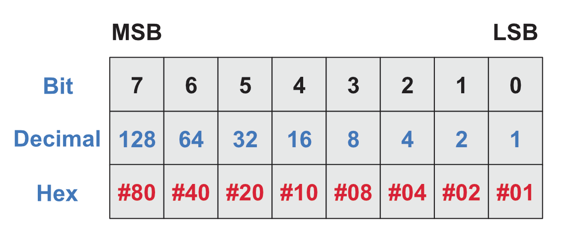
The following contains info of relevant registers, remember the Most Significant Bit (Bit 7) is to the Left, the Least Significant Bit (Bit 0) is to the right.
Status Register 0 (ST0)
| BIT | Name | info |
|---|---|---|
| 0 | US0 – Unit Select 0 | Drive A or B (If Bit Set). |
| 1 | US1 – Unit Select 1 | Drive C or D (If Bit Set) – Not used on the Amstrad CPC. |
| 2 | HD – Head Address | Flag to indicate that state of the Head at Interrupt. |
| 3 | NR – Not Ready | Indicates the Drive isn’t ready to send or receive commands/data if you try to send/receive data. |
| 4 | EC – Equipment Check | Set if the Drive is unable to recalibrate or there’s an error with the drive unit. |
| 5 | SE – Seek End | Set when the SEEK Command has physically completed the move to Track X |
| 6 7 | IC – Interrupt Code | 6 = 0, 7 = 0 – Normal Termination of the Command 6 = 1, 7 = 0 – Abnormal Termination of the Command 6 = 0, 7 = 1 – Invalid Command Issued 6 = 1, 7 = 1 – Abnormal Termination during command as Ready State Signal Received. |
Status Register 1 (ST1)
| BIT | Name | Info |
|---|---|---|
| 0 | MA – Missing Address Mark | If the FDC can not find a valid IDAM before two revolutions of the disk (Index Pulsed). |
| 1 | Not Writeable | During a Write Operation, the Write Protect Signal was detected. |
| 2 | ND – No Data | If during a READ, WRITE or SCAN operation the Specified Sector could not be found. If during a READ ID command, the ID could not be read without an error. If during READ Diagnostic Command, the start sector could not be found. |
| 3 | Not Used | Always 0 |
| 4 | OR – Overrun | The Controller wasn’t serviced (Data sent or received) from software within a set time interval. |
| 5 | Data Error | CRC Failure in either the ID Field or the DATA |
| 6 | Not Used | Always 0 |
| 7 | EN – End of Cylinder | Set when trying to access a sector not on this track. |
Status Register 2
| BIT | Name | Info |
|---|---|---|
| 0 | MD – Missing Address Mark | Set if the FDC cannot find a Data Address Mark or Deleted Data Address Mark. |
| 1 | BC – Bad Cylinder | Related to the ND Bit in ST1, when the contents of the Cylinder ID Stored on the medium differs from the from data stored in the IDR. |
| 2 | SN – Scan Not Satisfied | During the SCAN command, if the Sector ID can not be found. |
| 3 | SH – Scan Equal Hit | If the Sector ID matched that of the SCAN Command, then this is set. |
| 4 | WC – Wrong Cylinder | Related to the ND Bit in ST1, when the contents of the Cylinder ID Stored on the medium differs from the from data stored in the IDR. |
| 5 | DD – Data Error in Data Field | CRC Error in the data read. |
| 6 | CM – Control Mark | Set during a Read Data or Scan Command, set if a sector contains a deleted data address mark. |
| 7 | Not Used | Always 0 |
Status Register 3 (ST3)
| BIT | Name | Info |
|---|---|---|
| 0 | US0 – Unit Select 0 | Status of the Unit Select 0 = A, 1 = B |
| 1 | US1 – Unit Select 1 | Status of the Unit Select 0 = C, 1 = D |
| 2 | HD – Head Address | Status of the Side Select (0 = Side A, 1 = Side B) |
| 3 | TS – Two Sided | Two Sided Drive Status? |
| 4 | T0 – Track Zero | Track Zero Detected |
| 5 | RY – Ready | The FDC Is Ready |
| 6 | WP – Write Protect | Write Protect Signal, 1 = WP |
| 7 | FT – Fault | Fault was detected. |


Little error here :
motoron
LD A,1
motorctl
LD BC,#7FAA ; FA7E should be better 🙂
OUT (C),A
RET
motoroff
XOR A
JR motorctl
LikeLiked by 1 person
Thank you, I’ve corrected it… Clearly I hadn’t had enough coffee when proof reading!
LikeLike
Thanks a lot. I was looking for such code at some point.
Note that patchrwd can be simplified, methinks :
patchrwd ; Patch Read Write Data
PUSH hl
PUSH af
LD (hl),e
INC hl
LD (hl),d
INC hl
LD (hl),e
INC hl
LD (hl),c
INC hl
LD a,(sectsize) ; Get Sector Size From XDPB
LD (hl),a ; Store It
INC hl ; Point To End Of Track
LD (hl),c ; Store Sector
INC hl ; Point To Gap Length
LD a,(gap3rw) ; A = Gap #3 For READ/WRITE
LD (hl),a ; Store It
INC hl ; Point To Data Length
LD a,(dataleng) ; A=Sector Length
LD (hl),a ; Store It
POP af
POP hl
RET
LikeLiked by 1 person