
Speedlock 1987
Welcome back, how are you doing? In this post (Post 314 as it turns out, I was going to call it something Pi related but…), I’m going back in time to my early hacking days. Back then I used to disassemble protection systems for a number of reasons… the mental challenge, transfer tapes to disks, then finall, find and create cheats for games, because… well I’m terrible at playing them. As a bonus magazines/publications and 3rd parties would publish them. If you ever owned main stream 8-Bit computers there’s a likely chance you’ll have come across or used my cheats without even knowing it!
In this post, I’m going to cover Speedlock ’87 a common fast loader tape protection system on the Z80 systems, though the focus will be on the Amstrad CPC.
I’ll cover this using old school tools I had back then.. Of course modern day emulators make the job of hacking/cracking software a doddle. I will use an emulator JavaCPC by my friend DevilMarkus, it’s a free download from https://sourceforge.net/projects/javacpc/ Though this tutorial will work on real hardware, or the emulator of your choice.
For this tutorial, all you’ll need it the following :-
- Amstrad CPC 6128 or Emulator set to 6128 mode (or 464 with extra RAM and Disk Controller).
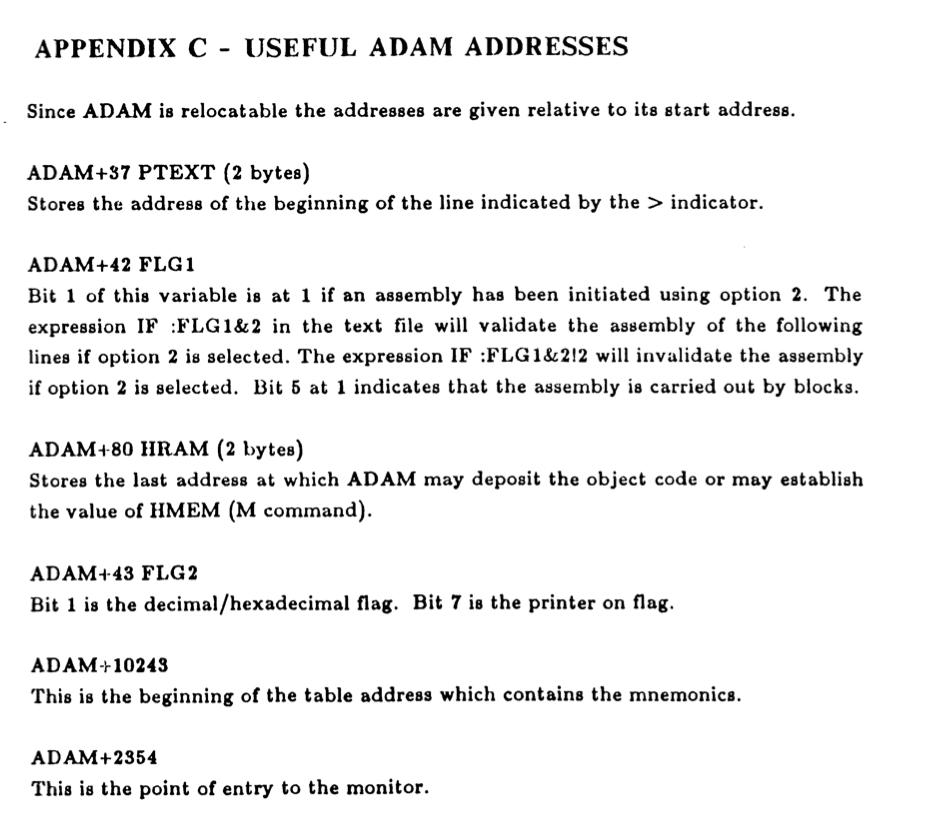
- ADAM Software (Assembler, Disassembler and Monitor), aka, DAMS in Europe.
- A copy of Codemasters Dizzy on Cassette or an original CDT File available via a google search.
- Some Z80 Assembler Knowledge
- A Rudimentary understanding of the Amstrad CPC
- My own routines and assembler.
This tutorial is not :-
- Assembly Tutorial for the Novice.
I will provide a DSK image on my GitHub Repo for Amstrad CPC Here: https://github.com/muckypaws/AmstradCPC
These will be filed under folder Blog/Speedlock17 you’ll find the DSK, CDT and Assembler files used.
Huge thanks to PSEGUY for his permission to include the ADAM tool in the disk image provided for this tutorial. You can find out more at his Git Repo here: https://github.com/pseguy/dams
If you don’t like typing too much code, I’ve provided the completed sections of code on the DSK Image which you can load up into the ADAM environment. There are some quirks with ADAM which I’ll cover in a separate post.
Why the Amstrad CPC 6128?
The CPC6128 was an ideal system for hacking, with its expanded 128kb of memory, meant there was space to add additional code or programs. The architecture of the machine also meant only 64kb could be addressable at any one time, this meant I could load my tools and assembler into one of the expanded RAM Banks knowing it would be protected from protection code being executed. An additional benefit included the ability to perform a soft reset whilst many a time I could recover my environment quickly and without loading everything up again.
Nomenclature
Many systems when referring to hexadecimal addresses prefix a Hex Value with &, 0x or $ and these are all valid. In the ADAM world, this system uses # instead, you will see reference to # addresses throughout, but know it means Hex Address or Hex Value. The Dollar $ symbol has additional meaning in ADAM, being the current address in assembler.
Compared to other Assemblers, ADAM doesn’t use “ for DEFM Statements (Saving bytes), but doesn’t allow leading spaces in messages. If you are following along with an emulator’s built in assembler or MAXAM ROM etc… you may want to add Quotes around DEFM messages. If you’re used to adding double quotes around DEFM it will fail in ADAM as it will assembler that as bytes too.
In addition I’ve created a video that may help with the article too.
Check your Cassette or CDT Image Works
Some basic house work before we begin.
First make sure the cassette loads normally. If you’re following along with a .CDT Image, make sure it’s an uncracked copy. Cassettes that are going on for 37+ years may have loading issues if not stored safely.
if you’re on a CPC with Disk Drive installed type the following :-
|TAPE
RUN"
I’m using my favourite CPC Emulator, JavaCPC https://sourceforge.net/projects/javacpc/ there are others available such as Caprice, WinApe, RetroVirtualMachine etc, though for development features this is pretty handy to have in your toolkit. It works pretty well on my ageing iMac.
The main reason I’m doing this on an emulator is it’s easier to capture screen shots than photographing/videoing my real machine with the CRT Beast sat on my desk.

Follow Along Video
Reading text can be boring… in parallel I’ll be creating a youtube video tutorial which is embedded below if you feel more comfortable watching or need further clarity on what I’m doing.
Reconnaissance
Preparation is key with any hack, in addition to understanding your target and architecture of the platform software is deployed. The principles are the same as modern day hacking, except the target environment was less complex in the 80’s than it is today.
For all tape based games, they will always require an initial loader created by the Amstrad Tape System. This could be a basic or binary program, but either way it needs to load
Rewind the cassette and type :-
|TAPE
LOAD""

You’ll see the Memory Full error. This tells us the initial loader is Binary (No BASIC Front End). The challenge is… the CPC doesn’t provide native tools to let us know at what memory and execution address the program loads.
I’ll cover writing your own in another article, for now, on the .DSK image there are two files.
- RSX.ADM (Source Code)
- RSX.BIN (Executable)
Determine the load address, filetype and execution address
To help determine the file reported fileinfo, we’ll use a simple RSX I cobbled up back in the 80s.
memory &a1ff
load"rsx.bin"
call &a200
|TAPE
|FINFO

That was easy! The cassette reports it’s a Binary File,
- Load Address = #3A43
- Length = #A6
- Execution Address = #3A43
- File Type = 2 (Binary File)
Why did I say reports? Some protection systems obfuscated and falsified the header information to try and trick us up, FlySpy was a classic example of this.
This RSX can give you file information for disk files too. Just provide the file name.

We now know where to start our hacking journey…
Fire up the Assembler…
Yeah, not the same effect as Gene Hunt firing up the Quatro… It’s time to start looking at some code…
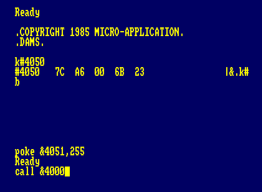
We’re going to fire up ADAM, our assembler and disassembler IDE. Since we’re using expanded memory, we’ll load it up into one of the RAM Banks. By default ADAM loads at Address #4000, you can load it to a different address by holding space as ADAM loads.
out &7f00,196
run"adam

I’ll cover the basics of ADAM in a later post, I’m going to assume you’re familiar with the environment. Press CTRL+B to toggle Hex and Decimal numbering. I prefer Hex, ensure that the top right changes from Dec. to Hex.
Given the address of the tape loader is within bounds of the CPC’s BASIC Memory Range, we could load the “Loader” from basic, or from assembler… Given we’re going to be working in assembler from now on, we may as well get started with simple loader code.
Below is simple boiler plate Firmware Load code, with the added extra, that we’re switching out of extended memory to load the code into main memory and switching back to extended memory to return to our Assembler environment. File: GetFirst.adm

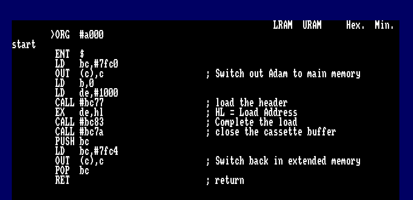
         ORG  #a000
start
         ENT  $
         LD   bc,#7fc0
         OUT  (c),c                     ; Switch out Adam to main memory
         LD   b,0
         LD   de,#1000
         CALL #bc77                     ; load the header
         EX   de,hl                     ; HL = Load Address
         CALL #bc83                     ; Complete the load
         CALL #bc7a                     ; close the cassette buffer
         PUSH bc
         LD   bc,#7fc4
         OUT  (c),c                     ; Switch back in extended memory
         POP  bc
         RET                            ; return
Remember to rewind your cassette, before you execute the code you may want to ensure that TAPE is selected for input. You can drop out of ADAM back to BASIC with the b command inside the IDE

|TAPE
Assemble the code with the A command and execute it with the J command.


And just like that, the loader code is in memory! We know that it’s #A6 Bytes in length (166 Bytes). Memory #3A43 – #3AE9 is our current target.
We’ll take a look at a hex dump and disassembly of the code.

Embedded within the code, is the name of the protection system used. Authors would use this to help us identify the system used, and I’m guessing a marketing strategy to show what’s out there in the real world. Protection system designers also known for their sense of humour, often leaving messages for hackers in their code.
Below is the disassembly of the first part of the initial loader. You may recognise a couple of firmware calls (#BC77, #BC83 and #BC7A) which suggests another piece of code is loaded. We’ll jump back to that shortly…
#3A43   EX   DE,HL          EB
#3A44   EX   (SP),HL        E3
#3A45   LD   A,D            7A
#3A46   OR   #10            F610
#3A48   LD   D,A            57
#3A49   INC  E              1C
#3A4A   PUSH DE             D5
#3A4B   CALL #3AB0          CDB03A
#3A4E   LD   A,(#3AE8)      3AE83A
#3A51   LD   B,A            47
#3A52   LD   C,B            48
#3A53   CALL #BC38          CD38BC
#3A56   LD   A,#FF          3EFF
#3A58   CALL #BC6B          CD6BBC
#3A5B   LD   B,#10          0610
#3A5D   LD   HL,#3A7C       217C3A
#3A60   LD   DE,#40         114000
#3A63   CALL #BC77          CD77BC
#3A66   PUSH BC             C5
#3A67   PUSH HL             E5
#3A68   PUSH AF             F5
#3A69   JR   NC,#3A79       300E
#3A6B   EX   DE,HL          EB
#3A6C   CALL #BC83          CD83BC
#3A6F   JR   NC,#3A79       3008
#3A71   CALL #BC7A          CD7ABC
#3A74   JR   NC,#3A79       3003
#3A76   DI                  F3
#3A77   POP  AF             F1
#3A78   RET                 C9
#3A79   JP   #00            C30000
At address #3A4B there’s a call to a routine at #3AB0, shown below…
This is simple colour palette initialisation, and a piece of sneaky code.
#3AB0 LD HL,#3AD5 21D53A
#3AB3 LD B,#10 0610
#3AB5 XOR A AF
#3AB6 PUSH BC C5
#3AB7 PUSH AF F5
#3AB8 LD B,(HL) 46
#3AB9 LD C,B 48
#3ABA INC HL 23
#3ABB PUSH HL E5
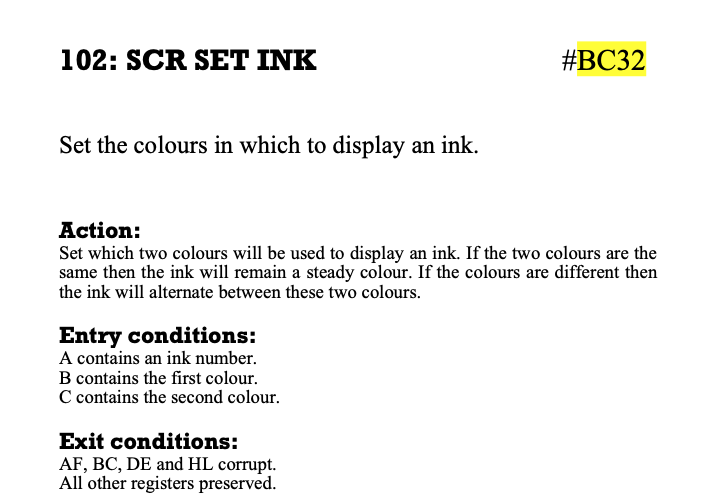
#3ABC CALL #BC32 CD32BC
#3ABF POP HL E1
#3AC0 POP AF F1
#3AC1 INC A 3C
#3AC2 POP BC C1
#3AC3 DJNZ #3AB6 10F1
#3AC5 LD A,(HL) 7E
#3AC6 PUSH HL E5
#3AC7 CALL #BC0E CD0EBC
#3ACA POP HL E1
#3ACB INC HL 23
#3ACC LD D,(HL) 56
#3ACD INC HL 23
#3ACE LD E,(HL) 5E
#3ACF EX DE,HL EB
#3AD0 LD (#AC00),HL 2200AC
#3AD3 RET C9
Colour Palette Initialisation
I’ll deal with this first since It’s straight forward.
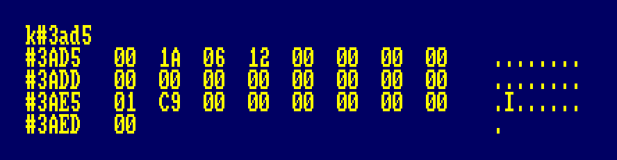
Basically a Table of data is defined at memory address #3AD5 containing the ink colours used.
- HL = #3AD5, The start of the Inks Table in Memory
- LET B = #10 (16 Decimal)
- A = 0, Start with INK 0
- Loop
- LET B = the contents of memory address pointed to by HL
- LET C = B, important as the CPC allowed “Flashing” inks.
- Set the Colour with Firmware call #BC32
- HL = HL + 1
- A = A + 1
- B = B – 1
- IF B <> 0 Loopback to Loop
This will loop sixteen times, increment A for each cycle of the loop. Since the game uses MODE 1, the colours the equivalent of BASIC Commands :-
INK 0,0
INK 1,26
INK 2,6
INK 3,18
Although the loop cycles through all sixteen colours, only the first four are relevant. This suggests a catch all piece of code for other games using this protection system.
Once the loop has completed the next section of code sets the Screen MODE. HL already points to the entry in the table.
#3AC5   LD   A,(HL)         7E
#3AC6   PUSH HL             E5
#3AC7   CALL #BC0E          CD0EBC
#3ACA   POP  HL             E1
This is the BASIC Equivalent of :-
MODE 1
Finally we have a sneaky piece of code…
#3ACB   INC  HL             23
#3ACC   LD   D,(HL)         56
#3ACD   INC  HL             23
#3ACE   LD   E,(HL)         5E
#3ACF   EX   DE,HL          EB
#3AD0   LD   (#AC00),HL     2200AC
#3AD3   RET                 C9
Memory from #3AD5 contains colour information for 17 bytes, 16 inks and one border colour. The code isn’t quite finished… The next two bytes in the table contain two additional bytes (Possible instructions).
DE is populated with data from #3AE5 and #3AE6, which is then written to address #AC00. The two bytes are #C9 and 00, opcode for RET (#C9) and NOP (#00). Address #AC00 is defined as reserved for Static Variables.
Decoding the Loader Part 1
Lets get back to the loader at #3A43 and make a start. The loader code starts off interestingly…
Swapping DE/HL Registers and then writing what ever was in HL to the current Stack Point…
#3A43   EX   DE,HL          EB
#3A44   EX   (SP),HL        E3
#3A45   LD   A,D            7A
#3A46   OR   #10            F610
#3A48   LD   D,A            57
#3A49   INC  E              1C
#3A4A   PUSH DE             D5
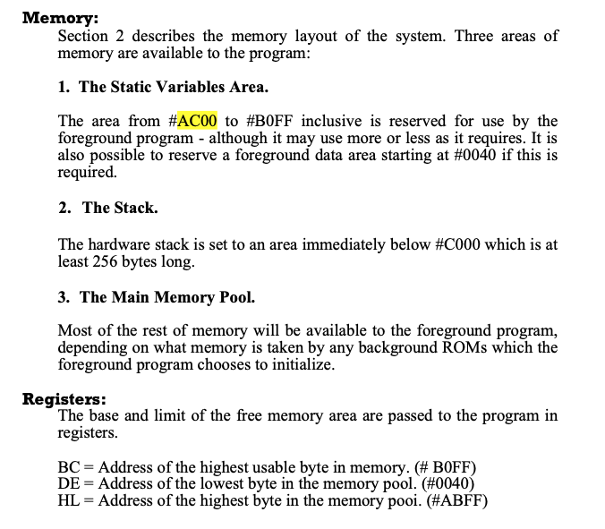
Spot the issue? DE/HL registers seem to be uninitialised… The devs used some knowledge from the firmware guide… see the snippet above, when a program is initialised, BC = Highest Byte of memory available to the program, DE = Lowest Address Available and HL = Highest in the memory pool.
HL = #ABFF
DE = #0040
BC = #B0FF
This is the first check you’re not tampering with the code… why? If you load the code into memory and then call it from outside the Firmware ROM routines, the program will corrupt itself and the game won’t load, since these registers won’t be initialised as expected.
Validating the start registers.
Don’t take my word for it! Lets run a simple test with some simple code.
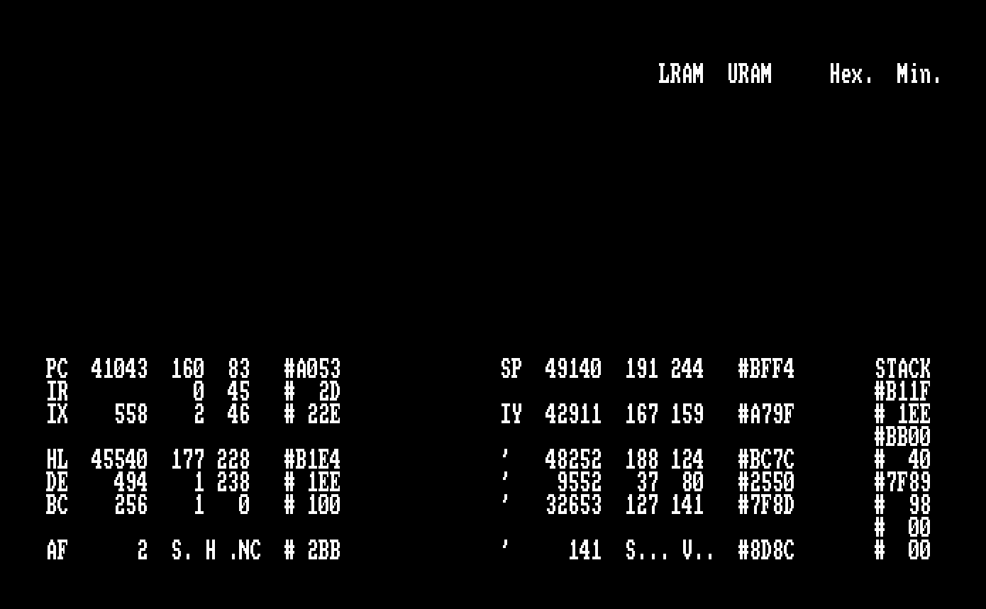
Take a look at GetRegs.asm, within ADAM I’ve assembled and written the source code to disk and the binary, as you can see below.
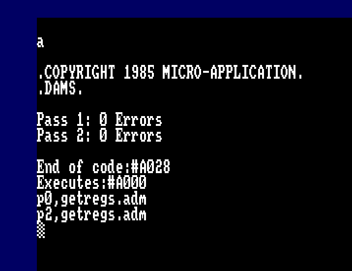
What does this program do?
Basically when run/executed the Registers are preserved in memory (AF, BC, DE, HL and SP) we’re not interested in IX, IY or the complementary registers. From BASIC we’ll run the code.
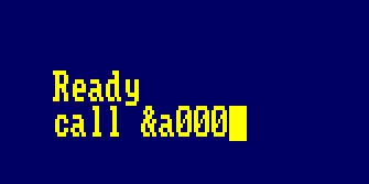
This will jump back to ADAM where you can view the registers. We can see that HL and DE are set similarly to below…

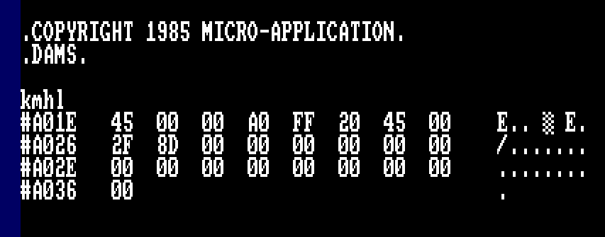
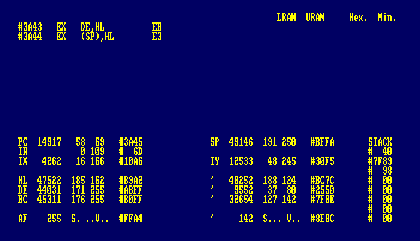
Next up… Lets RUN the binary we created and see the difference
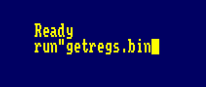

See the difference? HL, DE and BC are set as per the firmware specification, our Stack is pointing at address #BFFA and not #BFF8 since the program was loaded from firmware direct, rather than via the BASIC Interpreter.
First Load Part Two
Phew… that’s quite a bit to take in and we’ve not started on the second loader yet!
We now know the correct registers to set once the program has loaded and proven this using a simple program above. So we know how to set the registers before tracing the progam.
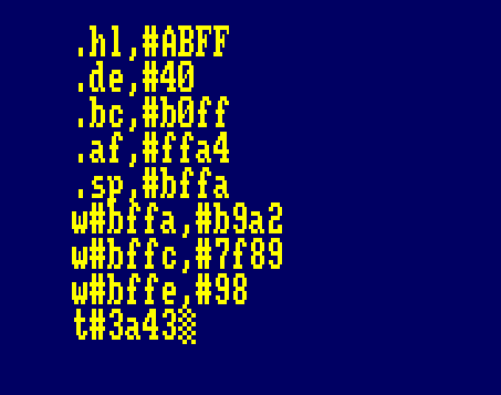
Using our load program from earlier, we’ll now load the first Dizzy Loader to memory, and then set the registers accordingly. The below commands are executed in ADAM
.hl,#ABFF
.de,#40
.bc,#b0ff
.af,#ffa4
.sp,#bffa
w#bffa,#b9a2
w#bffc,#7f89
w#bffe,#98
Swap the return address
First trick here is to swap out the RETURN address on the stack…. Followed by setting DE = #BB00, another address pushed onto the stack, (Another return address trick)…
#3A43   EX   DE,HL          EB
#3A44   EX   (SP),HL        E3
#3A45   LD   A,D            7A
#3A46   OR   #10            F610
#3A48   LD   D,A            57
#3A49   INC  E              1C
#3A4A   PUSH DE             D5
Now we set the screen colours and mode, (CALL #3AB0) plus that sneaky routine at overwrite the contents of #AC00. You will see later that this is a filler routine that serves as a method of “Self-Relocating Code” and advance the R – Register.

Control returns to #3A4E, where the Border colour is set and Cassette Messages are disabled. Calls to
#BC38 sets the border colour 0 (Memory address #3AE8)
#BC6B disables cassette prompts.
#3A4B   CALL #3AB0          CDB03A
#3A4E   LD   A,(#3AE8)      3AE83A
#3A51   LD   B,A            47
#3A52   LD   C,B            48
#3A53   CALL #BC38          CD38BC
#3A56   LD   A,#FF          3EFF
#3A58   CALL #BC6B          CD6BBC
At the Actual First Part Loader
Finally we’re at the area of code to load the next code loader.
- B = Length of Filename (16)
- HL = Memory Location of Filename
- DE = #40 start of 2Kb buffer.
#3A5B   LD   B,#10          0610
#3A5D   LD   HL,#3A7C       217C3A
#3A60   LD   DE,#40         114000
#3A63   CALL #BC77          CD77BC
#3A66   PUSH BC             C5
#3A67   PUSH HL             E5
#3A68   PUSH AF             F5
#3A69   JR   NC,#3A79       300E
#3A6B   EX   DE,HL          EB
#3A6C   CALL #BC83          CD83BC
#3A6F   JR   NC,#3A79       3008
#3A71   CALL #BC7A          CD7ABC
#3A74   JR   NC,#3A79       3003
#3A76   DI                  F3
#3A77   POP  AF             F1
#3A78   RET                 C9

The JR NC,#3A79 is a check if the file loaded correctly or cancelled by the user, this will Jump to #0000, to soft reset the machine and erase the contents of the loader from memory. All the LOAD CALLS made to firmware will set the Carry Flag if successful.
Directly after the call to #BC77, The registers BC, HL and AF are pushed to the stack.
- HL = File Header Buffer Address (64 bytes of data)
- BC = Logical File Length
- AF = Flags and File Type (A = 2 and Carry Flag is Set – Important to know for later).
If you look at this sequence, AF is popped off the stack, HL and BC aren’t… A programming trick since the RET will actually return to address #B1FF which was pushed onto the stack… (The Cassette Header Buffer). Surely this can’t be right? Won’t this crash the loader…

It could be code, but… it’s not… we jump to #B11F the tape header


There’s a reason the second stage loader is called ! !… they also double for OpCodes! This method was a popular way for protection system designers to “Hide” additional code since the novice will either miss it, think it a mistake or not look here. The Amstrad Tape header allows a private use area and they took advantage of this fact. It’s not new… The first instance I recall using this, was with the Commodore VIC20, C16 and C64, designers used this trick … a lot!
That’s a lot to take in if you’re new to this, so let’s create a simple first stage loader…
First Stage Loader and Patch
To give us an advantage, we’ll create a first stage loader that loads our games First Stage Loader, and patch a section of memory to return control to our environment.
The ideal candidate for the “Patch” is address #3A76
- Final instructions executed before control passed to next program.
- DI, POP AF, RET (#F3, #F1, #C9) give us three clear bytes to insert our JUMP Instruction which also requires three Bytes
- It’s clean approach since all initialisation is complete without interruption.
Simply put :-
- Switch memory bank so everything occurs in first 64Kb RAM Block
- Load The Dizzy First Loader to Memory
- Patch #3A76 to return control to our IDE
- Initialise the Stack and Registers
- Simulate execution from a RUN”” command
- Execute the code the first stage loader #3A43
- Loads the Second Stage File from Cassette to Address #40
- Cassette Header Buffer loaded to #B1FF
- PUSH #B1FF to stack
- Would be the next executed routine
- Switch in Ram Bank where ADAM is located.
- Return to our IDE Environment
Technically we don’t need to preserve the Stack for this protection system, later systems we’ll look at you may do.
When hacking it’s always better to preserve as much as you can to avoid detection.
We also switch memory back to bank 0 (To protect our Assembler Environment – although not necessary at this stage, it’s good habit forming).
On returning control to our code, BC will be preserved, switch back in the RAM Bank to where ADAM is located, prior to returning control back to our Environment. Screen Colours and Mode will be set as will the second stage program be loaded into memory. since paper and ink are set to colours suitable we won’t modify these.
FirstStageLoader.ASM
         ORG  #a000
patch1   EQU  #3a76
patch2   EQU  patch1+1
start
         ENT  $
         LD   bc,#7fc0
         OUT  (c),c                     ; Switch out Adam to main memory
         CALL load
         LD   hl,stakdata
         LD   de,#bffa
         LD   bc,6
         LDIR                           ; Patch the Stack - Saves 1 Byte (Not Necessary)
         LD   a,#c3
         LD   hl,back
         LD   (patch1),a
         LD   (patch2),hl
         LD   hl,#abff
         LD   de,#40
         LD   bc,#b0ff
         LD   sp,#bffa
         JP   #3a43                     ; Execute the loader..
load
         LD   b,0
         LD   de,#1000
         CALL #bc77                     ; load the header
         EX   de,hl                     ; HL = Load Address
         CALL #bc83                     ; Complete the load
         CALL #bc7a                     ; close the cassette buffer
         PUSH bc
         LD   bc,#7fc4
         OUT  (c),c                     ; Switch back in extended memory
         POP  bc
         RET                            ; return
buffer   DEFS 3,0
stakdata DEFW #B9A2,#7f89,#98
tocopy
         ORG  #be80
back
         PUSH bc
         LD   bc,#7fc4
         OUT  (c),c
         POP  bc
         POP  af
         JP   #4000                     ; Back to ADAM
I chose address #3A76 since this provides three bytes clearance to complete the loading sequence, and the JP instruction needs three bytes.
#3A76   DI                  F3
#3A77   POP  AF             F1
#3A78   RET                 C9
Run GetDec1.adm
We need to run this routine, but first we must ensure that the TAPE Is set for input. Drop back to BASIC using the IDE’s B command. Here I’ll use |TAPE.IN if DISC is the default, this way I can SAVE my edits to disk.
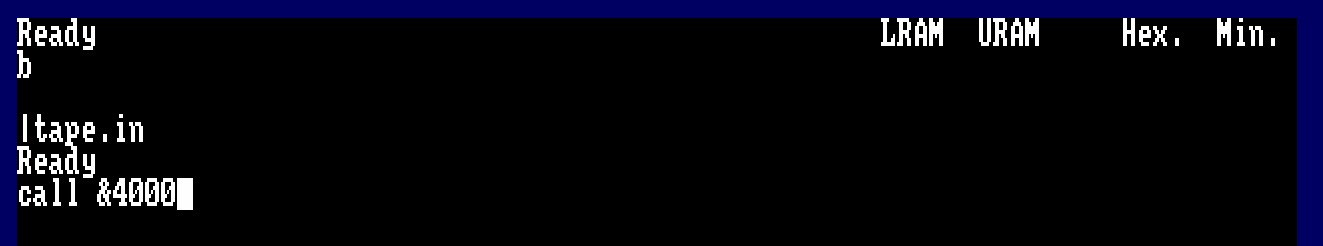
Let assemble the program and execute it.

Once control is returned to ADAM, you will see something similar if you switch to T (Trace).
You can see the Stack shows the next return address as #B11F (Remember from the previous set of PUSHES when loading the second stage? This is where the program will continue execution.
First Stage Decoder
Hang on… #B11F is the tape buffer? that contains the Tape header record?

Sure does! If you remember, the firmware defines the header block as below.
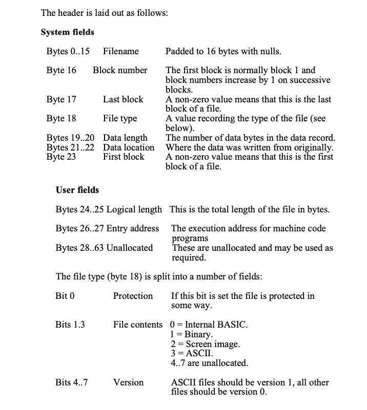
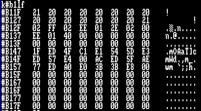
If you follow the 64 Bytes from #B11F you will see :-
| Byte | Description | Value |
| 0..15 | Filename 0..15 | ! ! |
| 16 | Block Number | 02 |
| 17 | Last Block | FF |
| 18 | File Type | 02 |
| 19-20 | Data Length | 01EE |
| 21-22 | Data Location | 0040 |
| 23 | First Block | 00 |
| 24-25 | User Field Logical Length | 01EE |
| 26-27 | User Field Entry Address | 0040 |
| 28-63 | User Data |
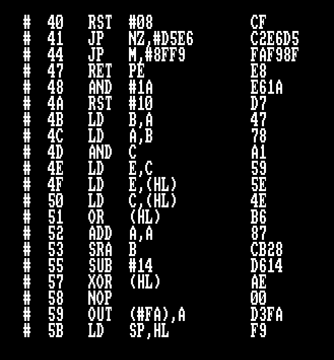
The authors have modified the header to contain some decoding routine. Did you think it odd the second stage loader has the filename “! !”? That’s no coincidence… Let’s take a look, after all, the first stage loader passes control back to #B11F.
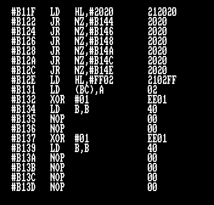
To the untrained eye, this looks like garbage code, a bunch of Jump Relative instructions, etc. Exactly what the authors wanted you to think… remember we popped AF before returning control… two reasons… A = 2 (FIle type). and… The Zero Flag is NOT SET, plus Carry is set… The LD HL,#2020 is a red herring, since the ASCII Code for ‘!’ = 33 which also happens to be a LD HL,xxxx instruction. fairly harmless to include in a tape header name… Control will actually jump to #B144

We have a total of 64 Bytes for the Tape header, so memory from #B11F and #B15F are all in range for further scrutiny.
Now everything gets more interesting? why? our first decode routine is cpu timing critical…From the moment the R Register is initialised.
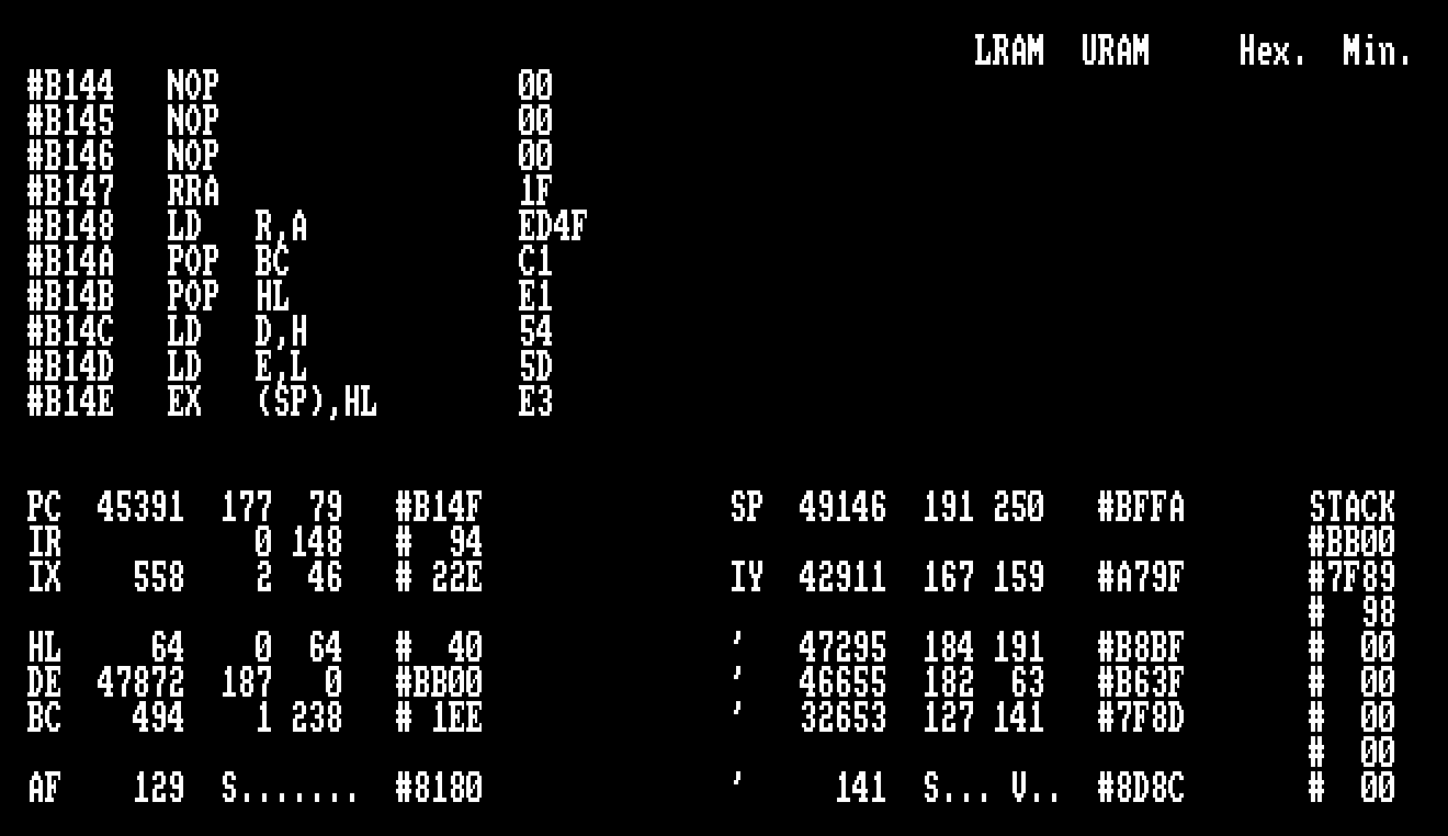
#B144   NOP                 00
#B145   NOP                 00
#B146   NOP                 00
#B147   RRA                 1F
#B148   LD   R,A            ED4F
#B14A   POP  BC             C1
#B14B   POP  HL             E1
#B14C   LD   D,H            54
#B14D   LD   E,L            5D
#B14E   EX   (SP),HL        E3
#B14F   LD   A,I            ED57
#B151   CALL PO,#AC00       E400AC
#B154   LD   A,R            ED5F
#B156   XOR  (HL)           AE
#B157   LD   (HL),A         77
#B158   LDI                 EDA0
#B15A   RET  PO             E0
#B15B   DEC  SP             3B
#B15C   DEC  SP             3B
#B15D   RET  PE             E8
#B15E   NOP                 00
#B15F   INC  BC             03
Ignore the first few NOP instructions, they’re irrelevant and filler to allow the header to contain this code.
A is shifted Right or divide by 2 to become the value #81.
What? surely a right operation is divide by 2? and 2 divided by 2 is 1 last time I took a maths lesson…
The RRA instruction is one you want to thank… when the file was loaded, the Carry Bit was set to indicate a successful load, the RRA instruction will Rotate Right Accumulator but will also shift the Carry Bit into the Most Significant bit.
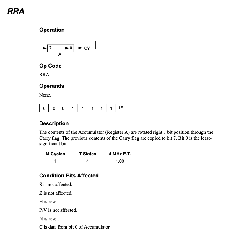
The R register is key, it increments in value depending on instructions executed by the Z80 processor. It is predictable based on the op codes/instructions being run (Provided Interrupts are disabled). If we introduce code that’s not part of the original design, R will quickly go out of sync and hold a different value at run time which means decoding the data will corrupt itself very quickly.
Of course we can only rely on time sensitive instruction execution when Interrupts are disabled.
The code initialises the following :-
- R = #81
- BC = #1EE
- HL = #BB00
- DE = HL = #BB00
- Swap Top of Stack with #40
- Return Address is now set to #BB00
R is initialised with the Value #81, BC and HL are popped off the stack, BC = #1EE, HL = #BB00, DE = HL before finally swapping that Stack Value #40 from the first stage loader with the length #BB00

At the TOP of the STACK is the original return address #B11F. this would have been executed had the RET instruction was still there. To continue our trace we need to increment the Stack Pointer by two, add two to your Stack Pointer, here it’s #BFF4 so #BFF6…
Press Q to go back to the IDE and enter.
.sp,#BFF6
t#b11f

We know the start parameters for the decode session… Unfortunately one of ADAM’s limitations is that it does not correctly calculate/preserve the R register with each instruction, so we’ll have to do some additional code shortly, but trace it through to see what’s happening for your understanding (The decoded code will be corrupt).

The CALL PO,#AC00 is smart in that it wastes a few cycles and sets the stack up for the return address to #B154. A simple trick for self-relocating code, meaning it could be run anywhere in memory.
Say what now? If we trace the code correctly from #B144 we see the following
- BC = #1EE
- DE = #BB00
- HL = #40
- Return Address on Stack is now #BB00

Remember, the call to #AC00 pushed the RETurn address #B154 to the stack. If we modify the stack to point two bytes lower, we can see this is true. The instructions later in the decode routine will decrement the Stack Pointer by two IF BC > 0, the RET will jump back to #B154 to continue the loop. Sure they could have used a JR OP Code, but… this particular technique also acted as a tamper detection/prevention method of execution.

Followed so far? What is this loop now doing?
- LET A = R
- LET A = A XOR with contents in memory pointed to by HL
- Write the Value in memory address point to in HL to memory address pointed to in DE
- HL = HL + 1
- DE = DE + 1
- BC = BC – 1
- Return if BC < 0000
- This will return to the address on the stack #BB00
- SP = SP – 2
- Remember that call to #AC00?
- The return address pushed on the stack is the next instruction after the call
- This points to the loop
- Remember that call to #AC00?
- RET
- Loop back to the beginning of the loop (LET A = R) above.
It could be written as :-
loop:
    LD A,R
    XOR (HL)
    LD (DE),A
    INC HL
    INC DE
    DEC BC
    LD A,C
    JR NZ,LOOP
Though for this purpose it won’t work since the timing will be off and R will contain a different value than expected on the XOR command.
Essentially, the code decodes the loader routine loaded at address #40 and copies it to memory location #BB00. This gives us a potential second problem… The Amstrad Firmware jump blocks are located here, which will force a crash if we try to return to BASIC or any program that relies on the firmware block. Thankfully ADAM Takes care of this for us!
Wondering about the RET PO instruction? The LDI (Load Increment) performs extra work for us, when BC (The counter) is decremented to zero, the P flag is set.

Bypassing the first decoder…
There’s a couple of methods we could use to remain in control of this decode routine. And here I’m going to copy the Speedlock code to our source code file and make appropriate modifications.
Rewind the Cassette to the beginning, the code on the .DSK is called GetDec1a.adm.

ADAM provides a method of doing this, using the H command. The important thing to remember here is to ensure our source code cursor is at the end of our source code. Jump into the editor, and move to the end of source code and add the label decode1

We're going to disassemble the code from #B147 to #B15E into source code using the following command.

H#B147  Instructs ADAM to disassemble to source from address #B147
Text?   Just hit return here as we're not including BYTE Data

END
#B15E

When complete the editor will open at the top of the newly imported source. We didn’t need the additional three bytes of Zero’s or NOP’s as they don’t affect the program code.
The original Speedlock Code at #B144 for comparison.

If we go back through our notes we know the following at the start of executing this routine to be True…
- AF = #2BB
- BC = #1EE
- DE = #BB00
- HL = #40
- Return Address on Stack is now #BB00 when the first stage decode is complete.
We’re going to make some changes to this code, but… we need to be mindful of OP Code CPU Timings where the R register is concerned. See the listing below. We don’t need to manipulate DE as we’re setting it and EX (SP),HL also takes the same amount of time as a NOP, we basically NOP these instructions out.
Why didn’t we just poke memory address #B14C, #B14D and #B14E with Zero bytes? we can and it’s more optimal this way, however I wanted to show you the basics of disassembling code to source as you’ll use this technique in later tutorials for more complicated protection systems.
back
DI
POP af
CALL decode1
back2
PUSH bc
LD bc,#7fc4
OUT (c),c
POP bc
JP #4000
adam EQU $-2
;
; add code here
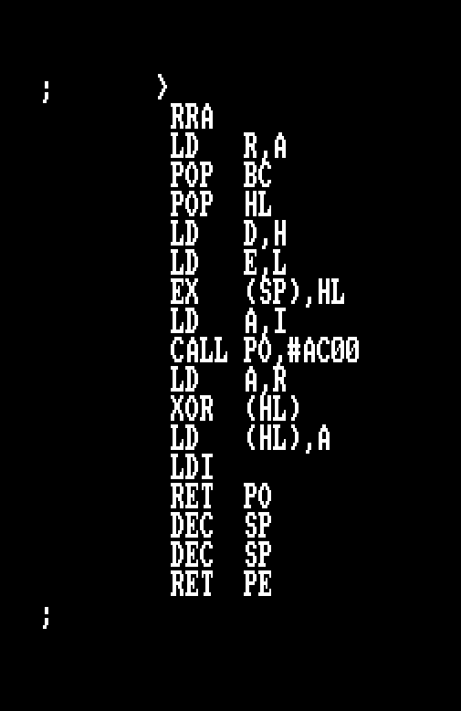
decode1
;
LD hl,back2
PUSH hl ; Return Control to ADAM Address
LD bc,#1ee
LD de,#bb00
LD hl,#40
PUSH hl
PUSH bc
;
RRA
LD R,A
POP BC
POP HL
NOP
NOP
NOP
LD A,I
CALL PO,#AC00
LD A,R
XOR (HL)
LD (HL),A
LDI
RET PO
DEC SP
DEC SP
RET PE
;
Rewind the Cassette tape and lets run this through once more, and if all goes well, we should see code at location #40 and #BB00 that match!
Did it crash after the second program loaded? We need to modify our Jump back to ADAM. If we call #4000 where ADAM was loaded, it uses a firmware call when initialising itself that will cause the crash… The workaround is simple… When we execute our code within the IDE, we POP the return address off the stack and modify our jump instruction.
         ORG  #a000
patch1   EQU  #3a76
patch2   EQU  patch1+1
start
         ENT  $
         POP  hl
         LD   (adam),hl

.
.
.

back
         DI
         POP  af
         CALL decode1
back2
         PUSH bc
         LD   bc,#7fc4
         OUT  (c),c
         POP  bc
         JP   #4000
adam     EQU  $-2
Full Source to GetDec1a.adm
         ORG  #a000
patch1   EQU  #3a76
patch2   EQU  patch1+1
start
         ENT  $
         POP  hl
         LD   (adam),hl
         LD   bc,#7fc0
         OUT  (c),c                     ; Switch out Adam to main memory
         CALL load
         LD   hl,stakdata
         LD   de,#bffa
         LD   bc,6
         LDIR
         LD   a,#c3
         LD   hl,back
         LD   (patch1),a
         LD   (patch2),hl
         LD   hl,#abff
         LD   de,#40
         LD   bc,#b0ff
         LD   sp,#bffa
         JP   #3a43
load
         LD   b,0
         LD   de,#1000
         CALL #bc77                     ; load the header
         EX   de,hl                     ; HL = Load Address
         CALL #bc83                     ; Complete the load
         JP   #bc7a                     ; close the cassette buffer
buffer   DEFS 3,0
stakdata DEFW #b9a2,#7f89,#98
back
         DI
         POP  af
         CALL decode1
back2
         PUSH bc
         LD   bc,#7fc4
         OUT  (c),c
         POP  bc
         JP   #4000
adam     EQU  $-2
;
; add code here
decode1
;
         LD   hl,back2
         PUSH hl                        ; Return Control to ADAM Address
         LD   bc,#1ee
         LD   de,#bb00
         LD   hl,#40
         PUSH hl
         PUSH bc
;
         RRA
         LD   R,A
         POP  BC
         POP  HL
         NOP
         NOP
         NOP
         LD   A,I
         CALL PO,#AC00
         LD   A,R
         XOR  (HL)
         LD   (HL),A
         LDI
         RET  PO
         DEC  SP
         DEC  SP
         RET  PE
;
Congratulations, the First Decode is complete! What’s next? game code?
First Decode Complete
When control is returned to our environment (Thankfully ADAM doesn’t rely on the firmware once it’s initialised – another good reason I loved this software back then). We can take a look at the code and memory.


Decode Routine 2
We’ve decoded the first stage and hopefully not fallen into the devs traps that would corrupt the next stage.
We know that control from Stage 1 Decoding returns execution at address #BB00. We also know that the code is time critical for instruction execution due to the use of the R register in decoding memory.
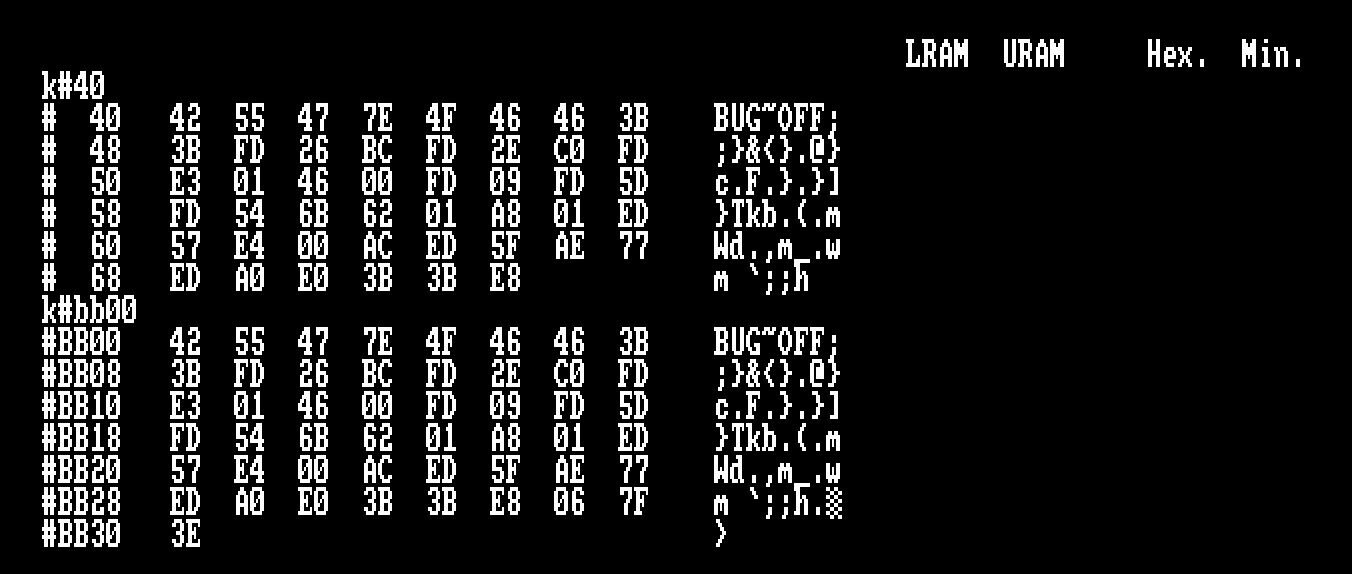
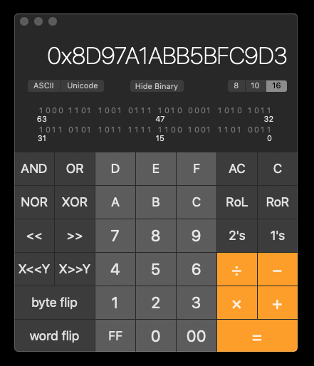
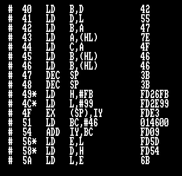
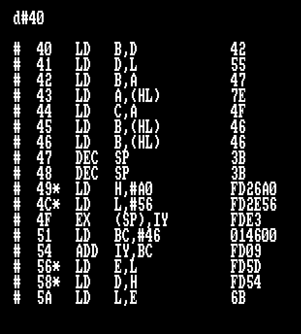
The devs left a message for us “BUG~OFF” which also are valid OP Code instructions, thankfully they’re not relevant to this next stage, since the registers will be set later on in code. Below is the second stage decoder code.
#BB00   LD   B,D            42
#BB01   LD   D,L            55
#BB02   LD   B,A            47
#BB03   LD   A,(HL)         7E
#BB04   LD   C,A            4F
#BB05   LD   B,(HL)         46
#BB06   LD   B,(HL)         46
#BB07   DEC  SP             3B
#BB08   DEC  SP             3B
#BB09*  LD   H,#BC          FD26BC
#BB0C*  LD   L,#C0          FD2EC0
#BB0F   EX   (SP),IY        FDE3
#BB11   LD   BC,#46         014600
#BB14   ADD  IY,BC          FD09
#BB16*  LD   E,L            FD5D
#BB18*  LD   D,H            FD54
#BB1A   LD   L,E            6B
#BB1B   LD   H,D            62
#BB1C   LD   BC,#1A8        01A801
#BB1F   LD   A,I            ED57
#BB21   CALL PO,#AC00       E400AC
#BB24   LD   A,R            ED5F
#BB26   XOR  (HL)           AE
#BB27   LD   (HL),A         77
#BB28   LDI                 EDA0
#BB2A   RET  PO             E0
#BB2B   DEC  SP             3B
#BB2C   DEC  SP             3B
#BB2D   RET  PE             E8
Remember, the code is timing critical, so any modification that throw the R register out will result in corrupt decode for the next stage.
#BB07   DEC  SP             3B
#BB08   DEC  SP             3B
#BB09*  LD   H,#BC          FD26BC
#BB0C*  LD   L,#C0          FD2EC0
#BB0F   EX   (SP),IY        FDE3
#BB11   LD   BC,#46         014600
#BB14   ADD  IY,BC          FD09
#BB16*  LD   E,L            FD5D
#BB18*  LD   D,H            FD54
#BB1A   LD   L,E            6B
#BB1B   LD   H,D            62
The devs added additional code to check it’s running in the memory location originally intended #BB00 by swapping out the previous Stack entry (#BB00) with IY and substituting a new return address of #BCC0.
The devs could have used LD IY,#BCC0, instead they opted to use “Undocumented Op-Codes”. For reasons I don’t remember, Zilog CPUs had Undocumented Instructions which allowed the manipulation of IX and IY at the MSB and LSB Level. Earlier Disassemblers may not always disassemble these bytes correctly, hence why ADAM places an asterisk against these opcodes. You can discover more here: http://www.z80.info/z80undoc.htm
These instructions act like LD IYH,value and LD IYL,value for the high and low bytes of a 16 bit word.
The ADAM assembler will only assemble these instructions using DEFB commands
We also see that BC is loaded with #46, which is the offset into the secondary stage loader code to start the decoding process.
Second Stage Decoding will begin at #BB00 + #46
- SP = SP -2
- Point the previous return address on the stack
- This will be #BB00
- LET IYH = #BC
- LET IYL = #C0
- This will be the next stage loader execution address.
- Swap the existing stack pointer with the contents of IY
- IY = #BCC0
- Top of Stack = #BB00
- Swap
- IY = BB00
- Top of Stack = #BCC0
- The next RET address
- LET BC = #46
- Offset into the next stage code
- LET IY = IY + BC
- IY = #BB46
Handling Decode 2
Those devs were pretty smart huh? Their Second Stage loader has more decoding to contend with, to make matters more interesting, it’s solely reliant on the Critical CPU Timing R register, meaning any code we introduce has to match and be CPU Time Perfect.
What approach will we take to handle it?
- Modify the actual loader code
- Copy the Decode Code to our program and modify it.
- Use the smart protection against itself!
The first two approaches will work, both require PUSHing the Length of Data Loaded and the Return Address to the Stack. You might instinctively think about NOPing the EX (SP),HL instruction. Try it and see what happens.
It’s been close to 37 years since I last tackled this system and whilst working through I over complicated the my initial approach, I did decode the next stage modifying decode routine 2, but…. remember the old mantra? “Less is More”… “Keep it Simple”…
Flaw with this Protection
Whilst the code is indeed CPU Time critical in decoding, there’s a major flaw with this system. If you remember, the decode routines will XOR bytes of data against the R register, which means it’s a straight forward XOR Cypher or Electronic Code Book if you know about DES Encryption standards. Why is this important? There’s no feedback to the decoding routine. The previous result doesn’t feed back into the decode mechanism.
What do you mean feedback?


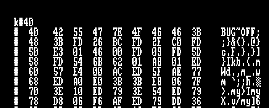
We’re going to XOR the first eight bytes from #40 in the pre-decoded data with the same block of data in the decoded data. Using a calculator.
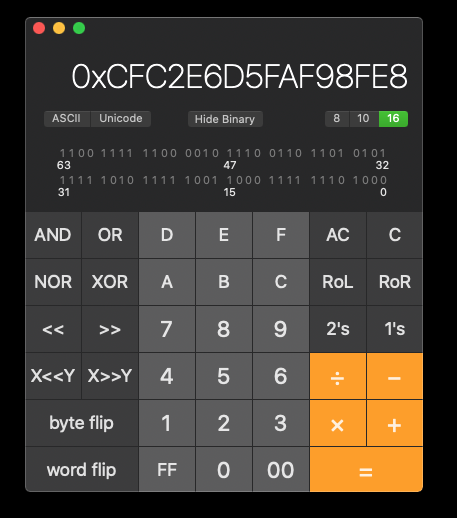
We take the encoded portion of the code starting from address #40 which starts #CF #C2 etc. and XOR it against the Decrypted Code at the same memory address #40 which reveals #42 #55 #47 etc.
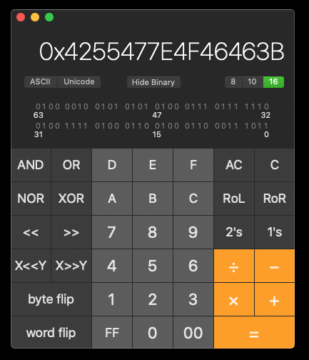
This gives us the bytes… #8D #97 #A1 #AB etc…
Do you see a pattern?
The seed starts at #8D (Remember R is initialised with #81 (So 12 R Cycles were used to get to this point), all subsequent XORs are SEED = SEED + 10.
It’s a constant. If the devs used the result of the last decoded byte back into their algorithm it would have complicated the matter for us, since any change in data would crash the program.
Since decoding is a constant we can work out what the XOR value required to patch the code. Rather than turn to maths, we’ll do this a much easier way. How?
Easy… see the piece of code with the two illegal op codes at memory #49 and #4C? This contains the return address from the decode routine itself #BCC0. We’ll load the Value 00 to locations #4B and #4E.

GetDec2.adm Listing
The listing below is the full listing from the file GetDec2.adm on the .DSK Image.
         ORG  #a000
patch1   EQU  #3a76
patch2   EQU  patch1+1
start
         ENT  $
         POP  hl
         LD   (adam),hl
         LD   bc,#7fc0
         OUT  (c),c                     ; Switch out Adam to main memory
         CALL load
         LD   hl,stakdata
         LD   de,#bffa
         LD   bc,6
         LDIR
         LD   a,#c3
         LD   hl,back
         LD   (patch1),a
         LD   (patch2),hl
         LD   hl,#abff
         LD   de,#40
         LD   bc,#b0ff
         LD   sp,#bffa
         JP   #3a43
load
         LD   b,0
         LD   de,#1000
         CALL #bc77                     ; load the header
         EX   de,hl                     ; HL = Load Address
         CALL #bc83                     ; Complete the load
         JP   #bc7a                     ; close the cassette buffer
buffer   DEFS 3,0
stakdata DEFW #b9a2,#7f89,#98
back
         DI
         XOR  a
         LD   (#4b),a
         LD   (#4e),a
         POP  af
         CALL decode1
back2
         PUSH bc
         LD   bc,#7fc4
         OUT  (c),c
         POP  bc
         JP   #4000
adam     EQU  $-2
;
; add code here
decode1
;
         LD   hl,back2
         PUSH hl                        ; Return Control to ADAM Address
         LD   bc,#1ee
         LD   de,#bb00
         LD   hl,#40
         PUSH hl
         PUSH bc
;
         RRA
         LD   R,A
         POP  BC
         POP  HL
         NOP
         NOP
         NOP
         LD   A,I
         CALL PO,#AC00
         LD   A,R
         XOR  (HL)
         LD   (HL),A
         LDI
         RET  PO
         DEC  SP
         DEC  SP
         RET  PE
;
We’ll modify our back routine to below, Run the loading routine again and see what pops up!
back
         DI
         XOR  a
         LD   (#4b),a
         LD   (#4e),a
         POP  af
         CALL decode1
back2
         PUSH bc
         LD   bc,#7fc4
         OUT  (c),c
         POP  bc
         JP   #4000
adam     EQU  $-2
You can see the code remains intact, the next execution address will now point to #FB99. Clearly we don’t want to put code in screen memory, but it does give us the vectors needed to XOR the address we do need!
XORing the Next Execution Address
What do we do? There’s options…
- Set another return address in our code by XORing two address bytes together or…
- Let the assembler take the strain!
Believe it or not, I’m quite lazy, especially if our assembler can take care of everything for us. We could use the memory address of our control routine will take over again and XOR the MSB/LSB Pair and pop that into memory, but if we modify our assembly we need to remember to recalculate this.
Thankfully ADAM takes care of this using inbuilt MACROS. We know the MSB (Most Signifiant Byte) is XOR’d with #FB and the LSB (Least Significant Byte) of the New address will be XOR’d with #99.
We use simple maths, back2 contains the address of the routine to return control. Divide this by 256 (Get the MSB), the exclamation mark ! is an XOR operator. We’ll XOR this with #FB
The LSB, we simply MASK the first 8 bits with &#FF then XOR with #99, poke memory with the result.
Since we’re no longer interested in the Decode Stage 1 Code, we simply complete what the original code did before patching. I.e once the encoded second stage loader code is in memory, we don’t worry about the first stage decoder, we’re poking our way in!
back
         DI
         LD   a,back2/256!#FB
         LD   (#4b),a
         LD   a,back2&255!#99
         LD   (#4e),a
         POP  af
         RET
back2
         PUSH bc
         LD   bc,#7fc4
         OUT  (c),c
         POP  bc
         JP   #4000
adam     EQU  $-2
GetDec2a.adm Listing
The full listing for the code is provided below :-
         ORG  #a000
patch1   EQU  #3a76
patch2   EQU  patch1+1
start
         ENT  $
         POP  hl
         LD   (adam),hl
         LD   bc,#7fc0
         OUT  (c),c                     ; Switch out Adam to main memory
         CALL load
         LD   hl,stakdata
         LD   de,#bffa
         LD   bc,6
         LDIR
         LD   a,#c3
         LD   hl,back
         LD   (patch1),a
         LD   (patch2),hl
         LD   hl,#abff
         LD   de,#40
         LD   bc,#b0ff
         LD   sp,#bffa
         JP   #3a43
load
         LD   b,0
         LD   de,#1000
         CALL #bc77                     ; load the header
         EX   de,hl                     ; HL = Load Address
         CALL #bc83                     ; Complete the load
         JP   #bc7a                     ; close the cassette buffer
buffer   DEFS 3,0
stakdata DEFW #b9a2,#7f89,#98
back
         DI
         LD   a,back2/256!#fb
         LD   (#4b),a
         LD   a,back2&255!#99
         LD   (#4e),a
         POP  af
         RET
back2
         PUSH bc
         LD   bc,#7fc4
         OUT  (c),c
         POP  bc
         JP   #4000
adam     EQU  $-2
;
As you can see the patch code is becoming shorter, and that’s a good thing, in hacking we need to patch software with the minimal effort required and to help with reducing detection.
We’ll run this code as we have previous and this time you’ll see the address that will be swapped onto the Stack has changed to our routine located at #A056

Tertiary Loader
Are we there yet? Nope…
As with any protection system, there could be multiple decode routines, before we get to the final loader code for the program/game.
Control has been returned to ADAM…
We know that the intended return address was #BCC0, is this more decoding routines or the game loader?
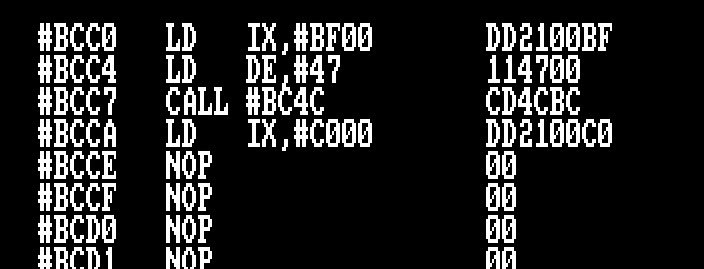
As it turns out, we’ve by passed the the protection system and all code has been revealed to us for full disassembly. This piece of code looks very suspiciously like a CALL to a tape loading routine, as we have a start address and what looks like a length.
The next LD IX instruction looks like the memory address to the screen which would match a loading screen next part, but… the memory beyond is NOP’d out. More code to be loaded here to continue? Nope, it’s a red herring!
The protection system pushes the value of IX to the stack (#BF00), which is the next execution address of the games loader.
We don’t need to do much at this point as ADAM will take care of this internally…
The code will load at address #BF00 and is indeed #47 Bytes.
From the IDE we can type the following :-
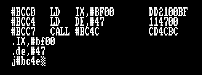
ADAM will execute the code at address #BC4E and return control to us. We bypass the PUSH IX instruction to ensure it works as intended.

You’ll see the familiar blue bars with the Speedlock header and data. When control returns to ADAM, remember to pause the cassette since the loader doesn’t switch the tape motor relay off.
The next set of loader code is successfully loaded to address #BF00 the final loader code. The tertiary loading code and thankfully the final piece of code!
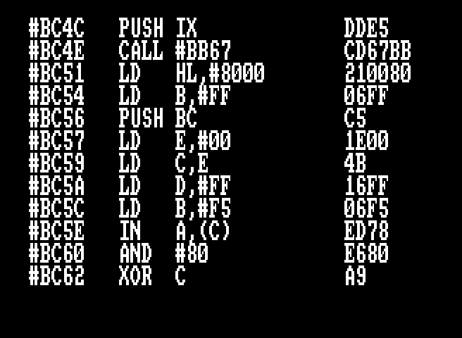
Final Loader
We’re nearly there, If you’ve reached this far, congratulations! A portion of the loader code is shown below.


As before,
- IX = Load Address
- DE = Data Length
- CALL #BB67 calls the tape loading Routines.
The loading screen is first up and easy to spot, the game code loads next and loaded from pointers at Memory Locations #BF3C and #BF3E Accordingly. A check is performed to see if #BF46 contains the value 1, if not there must be more code to load. Which is pulled from memory #BF40 and #BF42, before switching the cassette motor off and starting the game!
It’s likely this is generic/pattern code that could be reused simply by amending the table of addresses for each piece of software that employed this system
- IX = #C000
- DE = #4000
- CALL LOAD - Read in the Loading Screen
- IX = #40
- DE = #3862
- CALL LOAD – Read in Game Code at Address #40 for #3862 Bytes
- More code to load flag found
- IX = 38A3
- DE = #64AE
- CALL LOAD – Load More Game Code at Address #38A3 for #64AE bytes.
- Check the Flag at #BCBB, if NON-ZERO
- Execution address either set up or on the Stack so forward to #BF39 – Final Execution
- Otherwise…
- Switch off the Cassette Motor
- Get the next execution code from address #BF44
- This is #73B1
- Push this address onto the stack.
- Reinitialise the Firmware Block and execute the game code
- Return Address on the Stack

Decoding Complete
If you were to call or jump to the code at #BF00 the game will load and now you’ve learned the basic principles of how to decode and find the real Speedlock 1987 load code for games using this system.
Easy huh?
But wait… There’s more!
You’ve gone to all this effort, now what?
You’ll want to save an unprotected version of this game to disk so you can load it up quicker than before.
Using what we’ve learned, we’re gonig to create a Tape to Disk Utility specifically for this original game.
What have we learned?
- Speedlock 1987 consists of Three separate loading programs
- First is the Amstrad Binary File that loads at Address #3A43 (Though this address changes depending on the Game.
- Second Loading Amstrad Binary File called “! !” this loads initially at address #40 but will be copied and overwrite the Firmware Block.
- Sneaky decoding routine is stored in the Cassette Header Buffer.
- Third Loading program encoded using Speedlock’s System that will load to address #BF00
- To learn more about this protection we need to :-
- Intercept the initial code that starts the decoding routine after the second file has loaded off cassette.
- We can achieve this by strategically placing a JUMP Instruction just before execution of the first Decode routine.
- DI, POP AF, RET sequence
- The first execution starts at #B11F which decodes data from address #40 and copies the next stage decoder to address #BB00
- Execution Continues at address #BB00 to decode the next encoded program.
- We can achieve this by strategically placing a JUMP Instruction just before execution of the first Decode routine.
- Track and make note of the Stack Data to understand what’s happening under the covers.
- Load the final stage loader code, encoded under speedlocks cassette system.
- Intercept the initial code that starts the decoding routine after the second file has loaded off cassette.
- To Bypass the Protection System
- We learned that after intercepting the second stage loader, we can poke a couple of calculated XORd bytes to the address we want the loader to return control to ourselves.
TAPE to DISC
First up, we need to tidy up out hack code. To recap, we learned the following :-
- Design a program to load the initial loader from cassette.
- Add intercept code to return control to our program before the decode routines start.
- Execute the First Stage Loader code and await return of control.
- POKE Two Streatgic bytes with calculated data to return control back to our program.
- Load the Third Stage Loader Code
- Intercept the final execution address to return control to our program.
- Save the Loading Screen and Game Code.
Sounds easy with everything you learned? And it is…
We’re going to add some extra code, one a SAVE to Disk Routine, and a way to enable TAPE and DISK without having to return to BASIC using RSXs called within your assembly language program.
TAPE to DISC Transfer Program
Let start with the code…
         ORG  #a000
patch1   EQU  #3a76
patch2   EQU  patch1+1
start
         ENT  $
         LD   bc,#7fc0
         OUT  (c),c                     ; Switch out Adam to main memory
         LD   hl,rsxtape
         CALL rsxset
         CALL load
         LD   a,#c3
         LD   hl,back
         LD   (patch1),a
         LD   (patch2),hl
         LD   hl,#abff
         LD   de,#40
         LD   bc,#b0ff
         LD   sp,#bffa
         JP   #3a43
load
         LD   b,0
         LD   de,#1000
         CALL #bc77                     ; load the header
         EX   de,hl                     ; HL = Load Address
         CALL #bc83                     ; Complete the load
         JP   #bc7a                     ; close the cassette buffer
rsxset
         CALL #bcd4                     ; Request ROM and Address of RSX
         RET  nc                        ; command not found
         LD   (rsxwork),hl              ; Address of Command
         LD   a,c
         LD   (rsxwork+2),a             ; ROM where command located
         XOR  a                         ; No Parameters to Pass
         RST  #18
         DEFW rsxwork                   ; Point to work block
         RET
back
         DI
         LD   a,back2/256!#fb
         LD   (#4b),a
         LD   a,back2&255!#99
         LD   (#4e),a
         POP  af
         RET
back2
         LD   ix,#bf00
         LD   de,#47
         CALL #bc4e
         LD   hl,savecode
         LD   (#bf44),hl
         JP   #bf00
rsxtape  DEFM TAP
         DEFB "E"+#80
rsxdisc  DEFM DIS
         DEFB "C"+#80
rsxwork  DEFS 3,0                       ; RSX Work Space
savecode
         LD   hl,rsxdisc
         CALL rsxset
         LD   ix,#c000
         LD   de,#4000
         LD   bc,#0
         CALL save
         LD   ix,#40
         LD   de,#64Ae+#3862+1
         LD   bc,#73b1
         CALL save
         JP   #73b1                     ; Start the Game
save
         LD   hl,fname+5
         INC  (hl)
         LD   hl,fname
         PUSH bc
         PUSH de
         PUSH ix
         LD   b,fnamel
         LD   de,#c000
         CALL #bc8c
         POP  hl
         POP  de
         POP  bc
         LD   a,2
         CALL #bc98
         JP   #bc8f
fname    DEFM DIZZY0.BIN
fnamel   EQU  $-fname
The ORG address we can get away with remaining consistent throughout this tutorial, because the game code doesn’t extend beyond #9D51, remember the game ultimately loads at address #40 for #9D11 Bytes? (#40 -> #3862 + #38A3 -> #64AE), This last byte is loaded at #9D51, first address is #40 the length is #9D11
What does the final code do?
- Swap out the RAM Bank to Normal CPC Memory
- Call a new function to perform the BASIC Equivalent of |TAPE
- rsxset: Calls the Firmware #BCD4 to search for the command pointed to in HL
- Call our load function to get the first loader from cassette.
- Patch the loader to return control to our program and execute the initial loader code at #3A43
- Control returns to us at label back
- We then set the intercept address by XORing our programs second intercept as discussed earlier.
- Return control to the Speedlock Code and wait.
- Control Returns to back2
- Load the final loader code in Speedlock Format to address #BF00
- Patch our Address for the SAVECODE in address #BF44
- Jump and continue execution of Speedlocks original code and Wait.
- Control Returns to savecode
- rsxset: Set DISC mode so we can store our code to disk
- Save the Loading Screen
- Save the Game Code
- Jump to the Game
Are we there yet?
When you restart your Amstrad CPC, you will find on your disk two files, Dizzy1 and Dizzy2
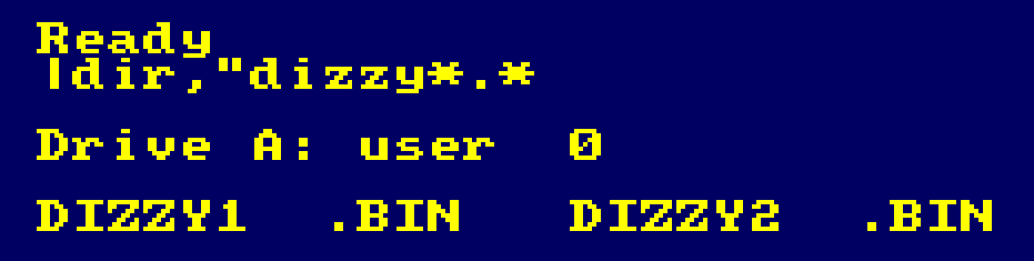

The 17Kb file is the loading screen and the 40kb file the game code, lets test to make sure we have everything and it works. We can load the title page with :-
LOAD”DIZZY1.BIN” or LOAD”DIZZY1
And be presented with a screen below. so far so good, except the colours are off… Don’t worry we’ll correct that.

The game code next, given that its all binary and loaded at an address below BASIC reserved memory, you will need to use RUN”DIZZY2
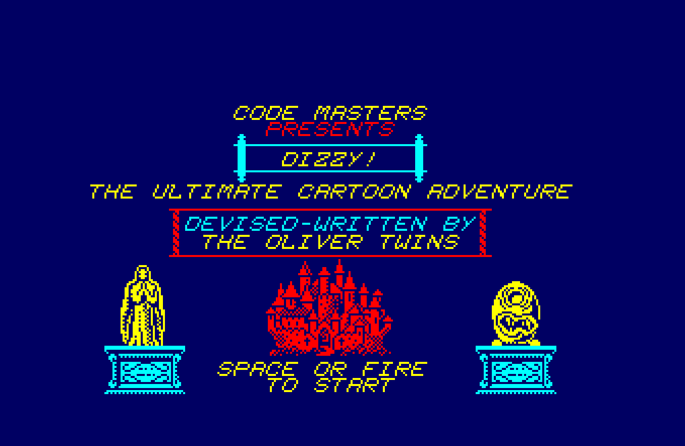
Spot the problem? yep, we need to sort the colours and the games border/info screen is missing too, even starting the game shows what’s missing.

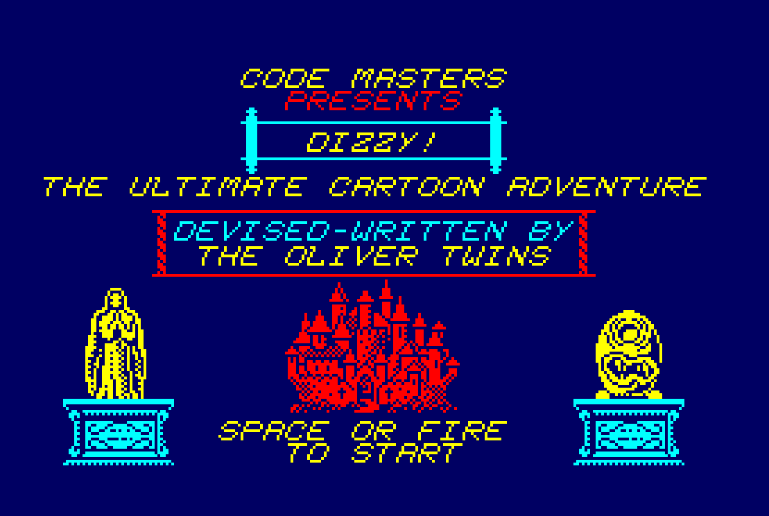
We just set the colours up right? no… and I’ll show you why… We’ll just set up the minimum for this test, set the Border, and INK 0 to Black and INK 1 to White. Now RUN”DIZZY2

What happened to the colours? If you remember right at the beginning of this exercise, when a program is executed directly from TAPE or DISC the Amstrad Operating System makes the maximum amount of memory available to the program by performing a mini initialisation. Default Colours are set and ROMS aren’t initialised.
There’s one final step…
You need to create a loader program.
Since the game code loads at address #40 and BASIC uses memory from #170, and command line entry uses address #40.
We can approach this one of two ways, create a BASIC Loader that wil load the game code higher in memory and copy this back to the original destination using an LDIR command, or we create a loader in Assembly. Given our focus is on assembly language, we’ll create a simple loader for our copied game.
The Game Loader
You have the basics on how to load code, but we’re going to need to cover off a trick or two. The final loader code is shown below, Though if your want to assemble it, you may see the following error.

Why? because ADAM initially only allows you to assemble to it’s configured HIMEM, which happens to be #A67C in my environment. To assemble code in higher memory, we need to modify ADAM.

Thankfully, the developer documented some key addresses, we simply drop back to BASIC, POKE &4051,&FF and jump back into ADAM. The code now assembles.
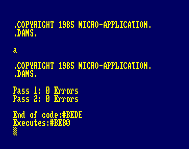
         ORG  #be80
start
         ENT  $
         DI
         LD   sp,#c000
         LD   hl,#abff
         LD   de,#40
         LD   c,7
         CALL #bcce                     ; Initialise AMSDOS ROM
         LD   a,1
         CALL #bc0e                     ; MODE 1
         LD   bc,0
         CALL #bc38                     ; Border 0
;
         LD   ix,inks
         LD   b,4
         XOR  a
setinks
         PUSH af
         PUSH bc
         LD   b,(ix+0)
         LD   c,b
         CALL #bc32                     ; SET INK
         POP  bc
         POP  af
         INC  a
         INC  ix
         DJNZ setinks
;
         CALL load
         CALL load
         JP   #73b1
;
load
         LD   hl,fname+5
         INC  (hl)
         LD   hl,fname
         LD   b,fnamel
         LD   de,#c000
         CALL #bc77
         EX   de,hl
         CALL #bc83
         JP   #bc7a
fname    DEFM DIZZY0.BIN
fnamel   EQU  $-fname
inks     DEFB 0,26,6,18
You’ll want to save both the source code and the binary loader.

Ok, let’s test it!

And finally the game loads, music plays, colours correct and you have successfully broken Speedlock 1987 for Dizzy on the Amstrad CPC. Congratulate yourself on a job well done!

Wait… What are these extra calls in the loader?
Ahh… you got me! Our loader is designed to run the game from disk from either…
- LOAD”DIZZY.BIN”,&BE80:CALL &BE80
- RUN”DIZZY.BIN
If we were to run the RUN”DIZZY” form, we have the issue of BASIC ROM initialisation, we need to re-enable the DISC ROM. On unmodified Amstrad Systems, AMSDOS Is always ROM7, we also need to ensure Lowest and Highest Memory Addresses are set (Won’t be correct if you CALL &BE80 from BASIC).
         ORG  #be80
start
         ENT  $
         LD   hl,#40
         LD   de,#abff
         LD   c,7
         CALL #bcce                     ; init DISK ROM

Next up, we set the screen mode and INKS to the values in the original loader.
;
         LD   ix,inks
         LD   b,4
         XOR  a
setinks
         PUSH af
         PUSH bc
         LD   b,(ix+0)
         LD   c,b
         CALL #bc32
         POP  bc
         POP  af
         INC  a
         INC  ix
         DJNZ setinks
.
.
.
inks     DEFB 0,26,6,18
Finally we load the title page and game code with two calls to load. Like the SAVE routine earlier we’ll just increment Byte 5 of the filename to save setting up extra name data.
Then that JUMP to #73B1 to start the game.
Conclusion
Speedlock 1987 was reliable speedload system for the Amstrad CPC and the ZX Spectrum, it cut down loading times significantly compared to the Amstrad native loader.
As a protection system, it was weak, the developers threw a bunch of clever tricks to try and protect the loader code, ensuring any tampering would result in a crash or corruption of code. This may have put off the beginner or novice. There was a reliance of knowledge about the CPC and it’s internal workings.
That said, the designers went on to improve both their tape and disc protection schemes over the years, adding in more complexity for hackers. You could say they were a trick ahead when it came to obfuscating their code.
That said, it also created a cottage industry in Tape to Disk programs and utilities sold by the likes of Nemesis, Goldmark and more, it also created bespoke services that would transfer cassette to disks for the public at a cost. Each time they improved their protection systems, it meant more upgrades could be sold and so on. Did it escalate piracy? we’ll never know for sure, after all, school kids learned earlier on using tape to tape decks gave them useable copies.
The Speedlock 1987 design was flawed in that feedback to the XOR loops wasn’t present, meaning tampering with the loader was trivial, with five pokes to gain full control. Three pokes for the first intercept, and two pokes for the final intercept. There was no further validation other than stack manipulation and CPU R Register Timing tricks. Had the designers used feedback in the code, any modifications would result in corrupt code, making our jobs trickier.
There was an additional trick that wasn’t covered, just after the load of the tertiary loader there’s a small piece of code that listens to the cassette tape before returning control to #BF00, it wrote data to address #8000 for 255 bytes… we’ll explore that in a future post, if there’s sufficient interest of course.
Tapes were easily copyable using TAPE to TAPE machines back then, and Speedlock 1987 wouldn’t detect this scenario. There was a beautiful final protection on the game Werner, which had what I called TONELOCK… A tone that was sampled on the cassette after the final byte was loaded to memory, that gave a decryption code to reveal the game. Tape copiers back then would mess this signal up resulting in game crashes. Equally though on genuine cassettes this wasn’t all that successful… I’ll cover that off at a later date if I can find my tapes.
That said, what the devs did do is leave open a simple method to create easy type-ins for magazine cheats, which I did regularly back in the 80’s. As a bonus I’ve included these for your amusement.
Things to do
What now? Practice your new found knowledge and practice some more until you no longer need to read this tutorial and apply your new found hacking skills to other cassettes using the same Speedlock 1987 system. You will find variations in load addresses and maybe the odd extra trick or two as the designers hone their skills further.
Thank you for following this far, I hope you’ve enjoyed it, or found it informative. I will look at creating more tutorials for protection systems as and when time permits.
Please leave your feedback in the comments section below, I would love to know your thoughts, errors, corrections or clarifications where I have not explained what’s happening. At the time of writing, I’ve documented another common protection system for the Commodore C16 in this post
Thanks for stopping by!
Bonus Cheats for Dizzy
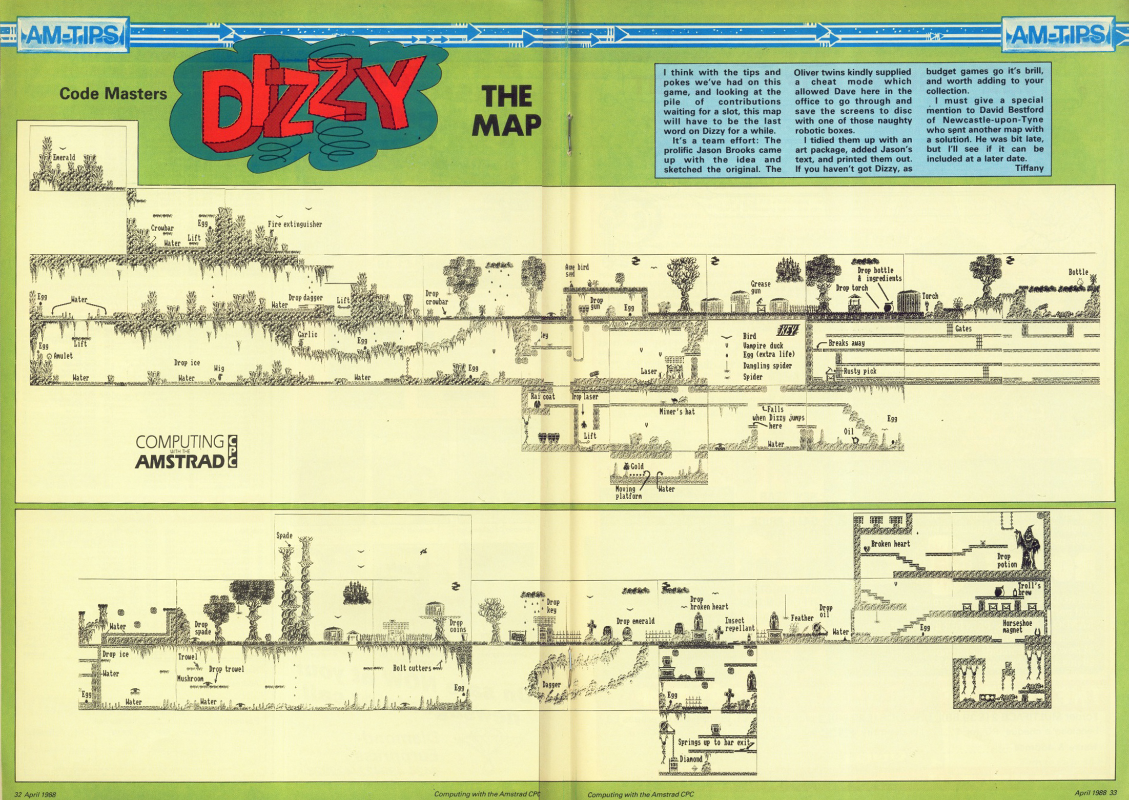
I was fairly prolific in the 80s across multiple platforms, much of my stuff was published in magazines and 3rd parties (Choice Cheats from First Choice Software, Nemesis, Goldmark etc), for example. In keeping with the game, these cheats I developed were First Published in Computing with the Amstrad CPC January 1988 was the first cheats for Dizzy. There was always a two month lead time from submitting a cheat to publication, and the magazine was usually dated a month or two ahead. The initial cheat would have been submitted shortly after release of the game in 1987. I loved the game so much, I created additional cheats, and a Map with solution that had a double page spread. My editor at the time, Ian C. Sharpe had enough of Dizzy cheats and so no more could be submitted. However there’s a story behind all this which I’ll reserve for a later post.
Feel free to type these in and run against your Cassette tape. Better still, with your new found knowledge, why not create a loader with the cheats embedded?
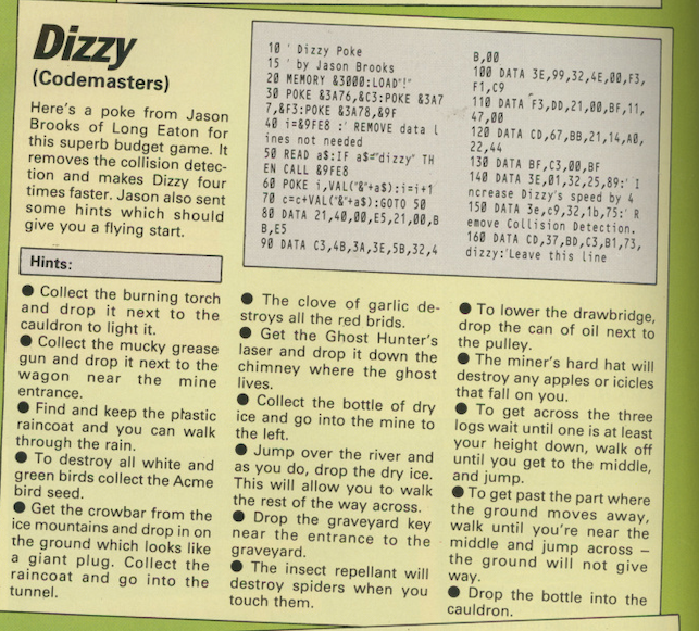
10 ' Dizzy Poke
15 ' by Jason Brooks
20 MEMORY &3000:LOAD"!"
30 POKE &3A76,&C3:POKE &3A77,&F3:POKE &3A78,&9F
40 i=&9FE8
50 READ a$:IF a$="dizzy" THEN END
60 POKE i,VAL("&"+a$):i=i+1
70 c=c+VAL("&"+a$):GOTO 50
80 DATA 21,40,00,e5,21,00,bb,e5
90 DATA c3,4b,3a,3e,5b,32,4b,00
100 DATA 3e,99,32,4e,00,f3,f1,c9
110 DATA f3,dd,21,00,bf,11,46,00
120 DATA cd,67,bb,21,14,a0,22,44
130 DATA bf,c3,00,bf
140 DATA 3e,1,32,25,89:' Increase Dizzys Speed by 4
150 DATA 3e,c9,32,1b,75:' Remove Collision Detection
151 DATA 21,00,00,22,d7,78,22,de,78:' See the screen being drawn
152 DATA af,32,3a,95,32,37,95:'Infinite Lives
160 DATA cd,37,bd,c3,81,73,dizzy


This is actually amazing article! Thank you so much 🙂 I really enjoyed it! I have a question… Have you ever tried to examine the copy protection of Dizzy II treasure island? It comes with Hexagon Disk Protection, according to cpc-power is type 3.
LikeLiked by 1 person
Thank you, brilliant and detailed article! Played around with this stuff as a kid around 1990. Forgotten most details now, but one other trick that bypassed many tape loader protections was to use the special bank switching mode that mapped the whole second 64k (mode &c2) instead of 16k at a time. You would start after a clean reset by copying the first 64k to the second 64k, 16k at a time (just to initialise the important bits), then “out &7f00,&c2”, and run the game from tape normally (blind IIRC since screen memory always displays from the first 64k). With many games they wouldn’t touch the bank controls during loading, but after loading they would call some ROM reset function (don’t remember the details), and that would switch back to the normal banks, leaving the full de-protected game code in the second 64k, preserved after the next reset, and then you could search for the ROM reset call. If you pre-filled memory with “rst 0” instructions it would increase the chance that you’d quickly get back to a clean reset when the banks were swapped back. Did many many tape to disk conversions that way!
LikeLiked by 1 person
The technique you described was used by HE Haxwell (Aka Tony Bethell) back in the day. I wrote code to deprotected Appleby Protection System which uses a random amount of 75-125 decryption routines before their loader. Tony and I were friends but also in competition with each other. I approached this to allow 464 users to write games to disk, and gave it away for free as part of the Bonzo Super Meddler tool set. Tony approached it the way you describe, meaning less faff around updates to the protection code and straight into the loader post firmware and rom reset. He proudly sent me a copy of his solution on disk including his unique protection system challenging me to break that 😂. The only downside was using the extra ram banks, the CPC was hardcoded to render the screen from the first 64Kb block of RAM so the user wouldn’t see the loading screen during the first pass.
Interestingly, one of the few games I created a cheat for but couldn’t work out a method for 464 users was PacLand. The protection used all 64kb to decode itself, so patching it resulted in corruption of the game itself.
I was able to achieve this with bank switching as you describe, but for magazines back then they wanted solutions that didn’t rely on extra hardware.
I take it you were also on the scene back in the day? what name did you go by? would love to see our work.
LikeLike