
3D Printer – X,Y and Z Axis Calibration
A common mistake when calibrating your printers X, Y and Z Axis is to print a 20mm calibration cube from Thingiverse, measure the dimensions with Callipers and make adjustments to your step rates.
I too was simply following instructions… Whilst that method may appear to work and it did print a perfect 20mm cube, it doesn’t take into account the materials expansion/contraction ratio.
I’m informed by the professionals the correct method is to measure the actual head movement and calculate your steps accordingly.
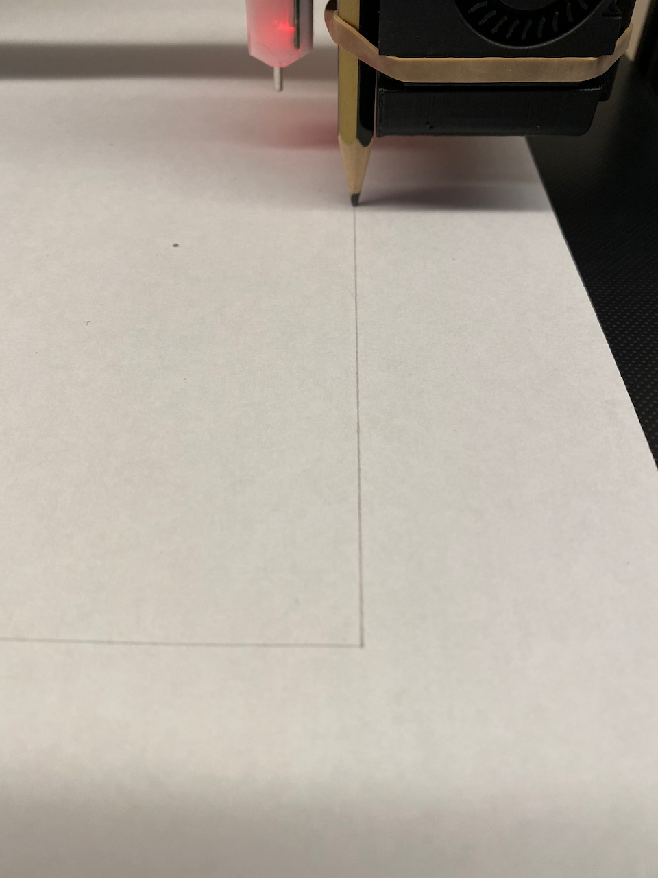
Achieving this is straight forward. Make sure your printhead has cooled down and attach a pencil. I used an elastic band, though you may need to get creative with your printer. Clip a piece of paper to the print bed and enter your printers Axis movement menu.
From the printer menu, I requested an X Movement of +100mm and a Y Movement of +100mm.
Using digital callipers, measure the actual distance travelled by the print head.
For the Z-Axis, I measured the current height from the bed to a fixed point underneath the print head before zeroing the callipers then requesting a movement of +100mm taking the same measurement. Though you can clip paper to the frame and move the pencil to the Z Axis and record movement that way.
To calculate your eSteps, the equation is simple,
(Amount Requested / Actual Amount) X Current Steps Value = New Steps Value

For example, if I requested 100mm on the X-Axis and the printer moved 98.5mm then the calculation would be (100/98.5) x 80.12 = 81.34, therefore you would enter 81.34 in your printers X-Steps set up.
Repeat the exercise again until your printer is moving the required distance.
And that’s pretty much all there is too it!


1 Comment »